question

renz avatar image
renz asked

BMV and inverter disagree on voltage, inverter shuts down under high load

Good day,

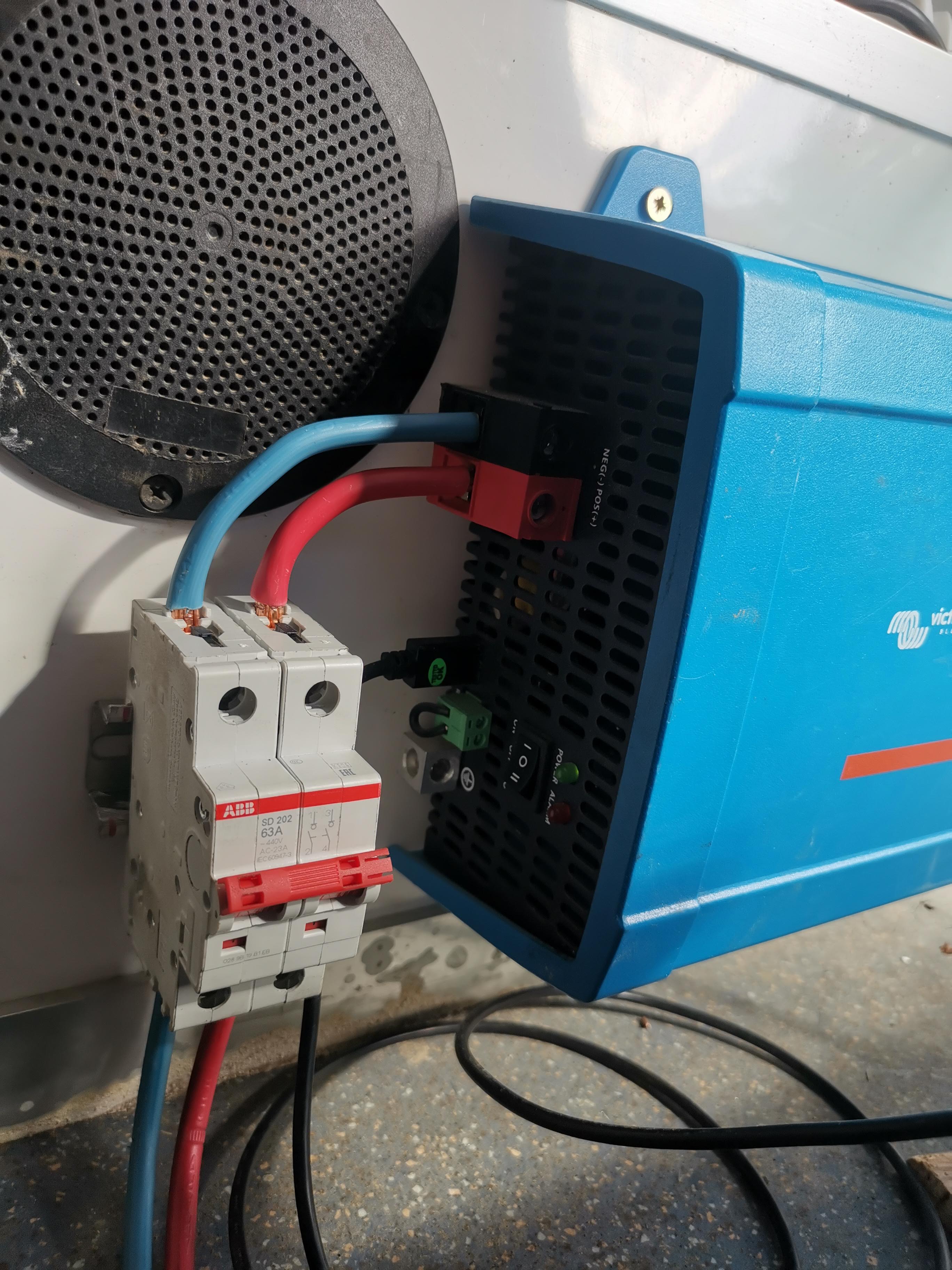
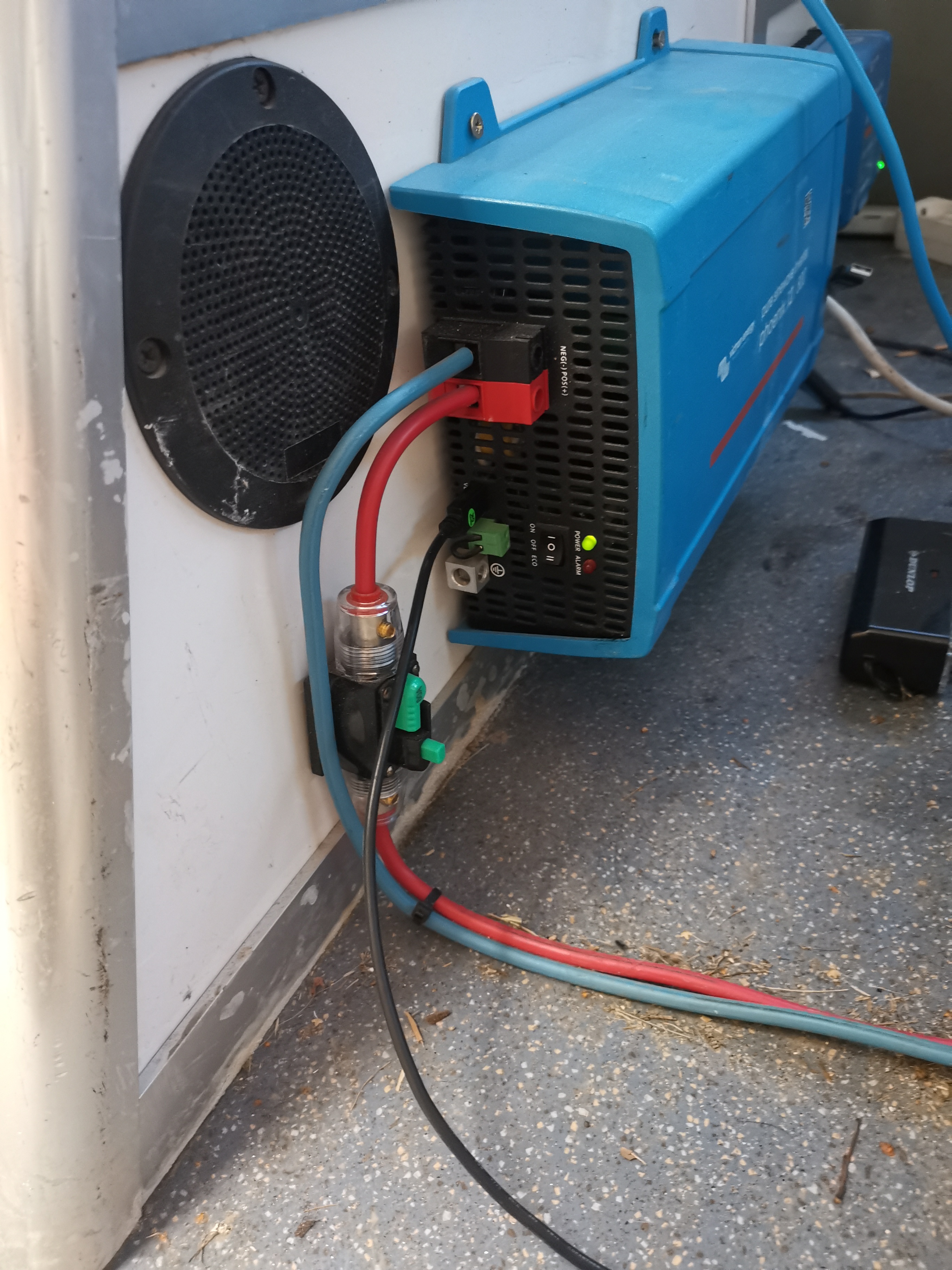
I'm having voltage discrepancy issues with my Phoenix 800 inverter and my BMV. For more info on that please feel free to check this post: https://community.victronenergy.com/questions/144128/phoenix-12800-shutting-down-not-overload-not-setti.html

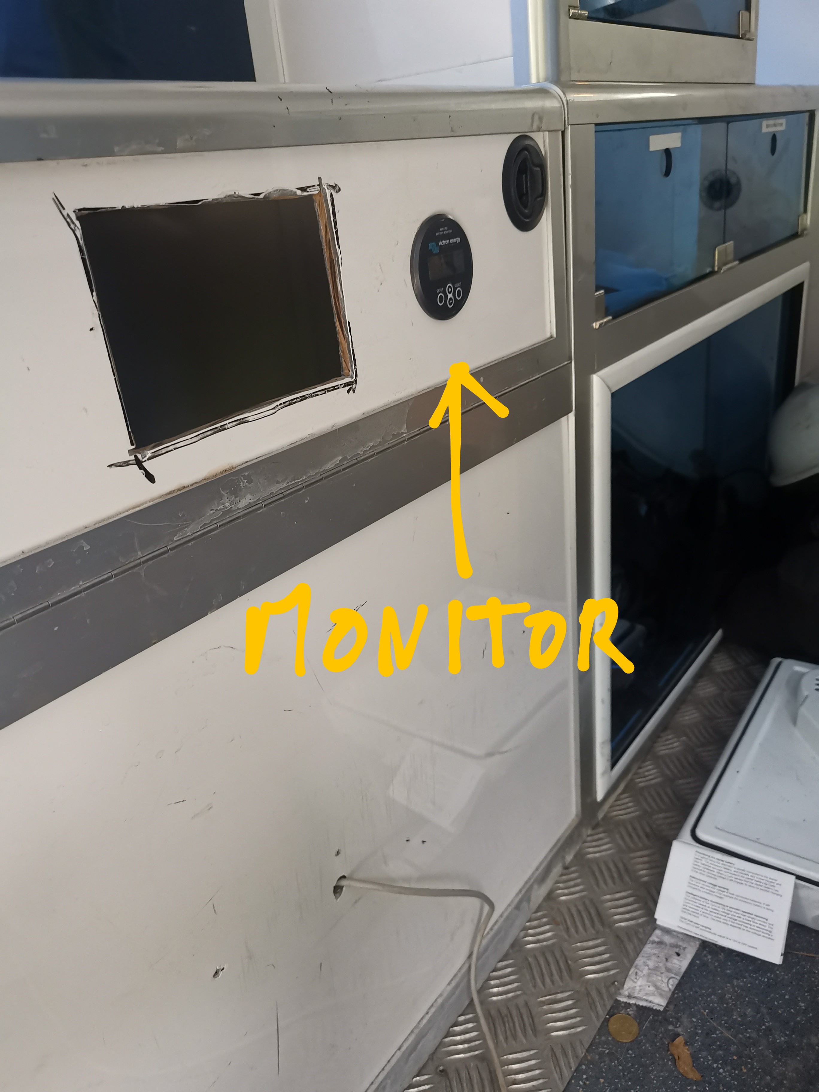
Can I get the BMV to set the voltage of the system in order to override whatever the inverter reads?

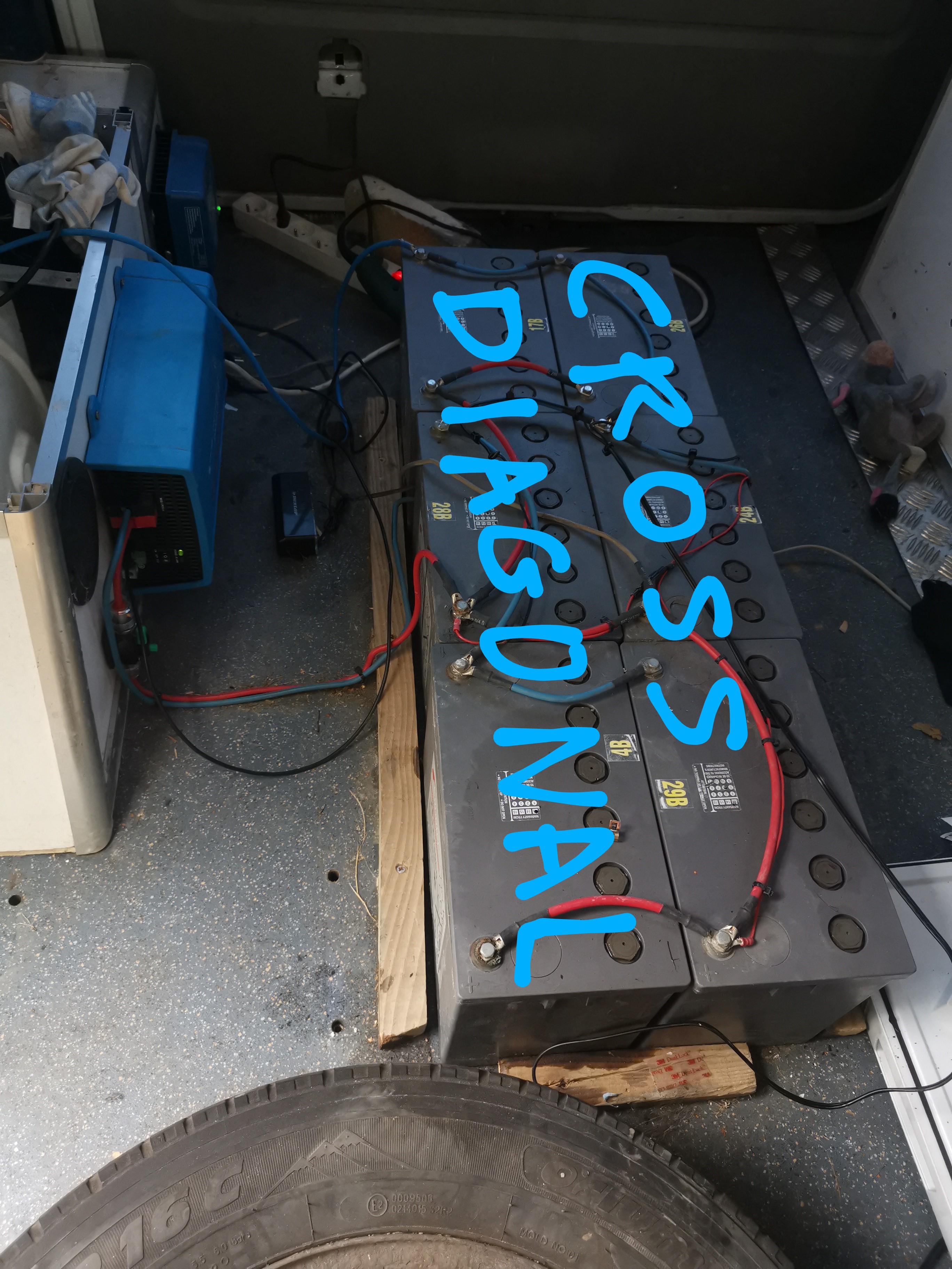
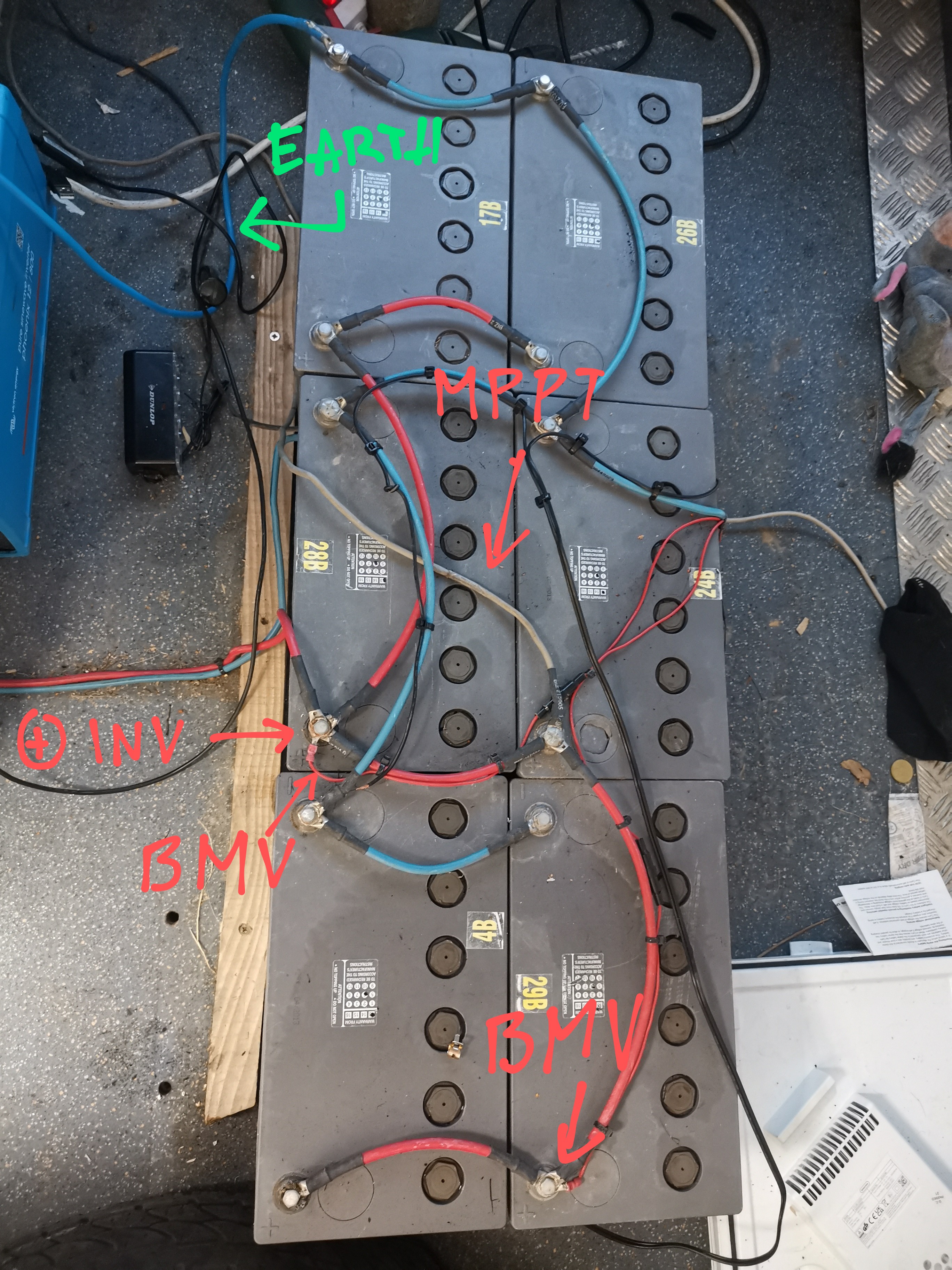
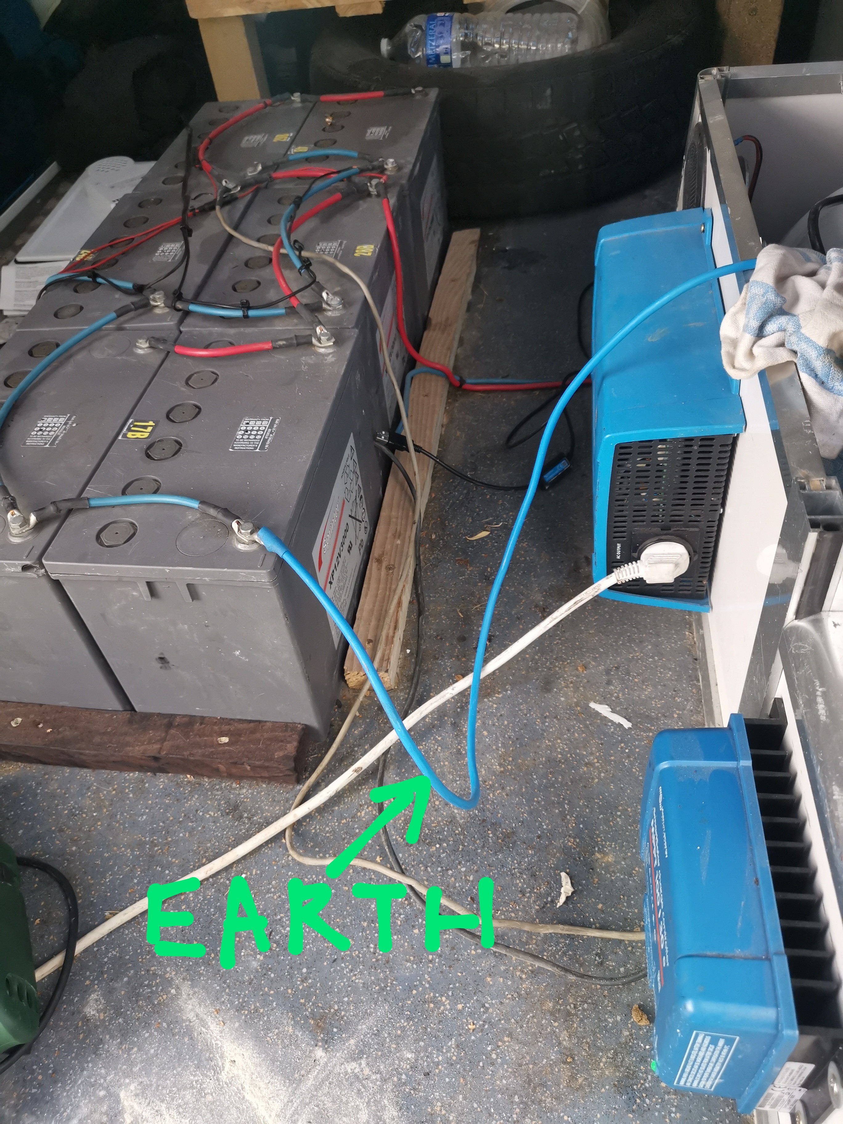
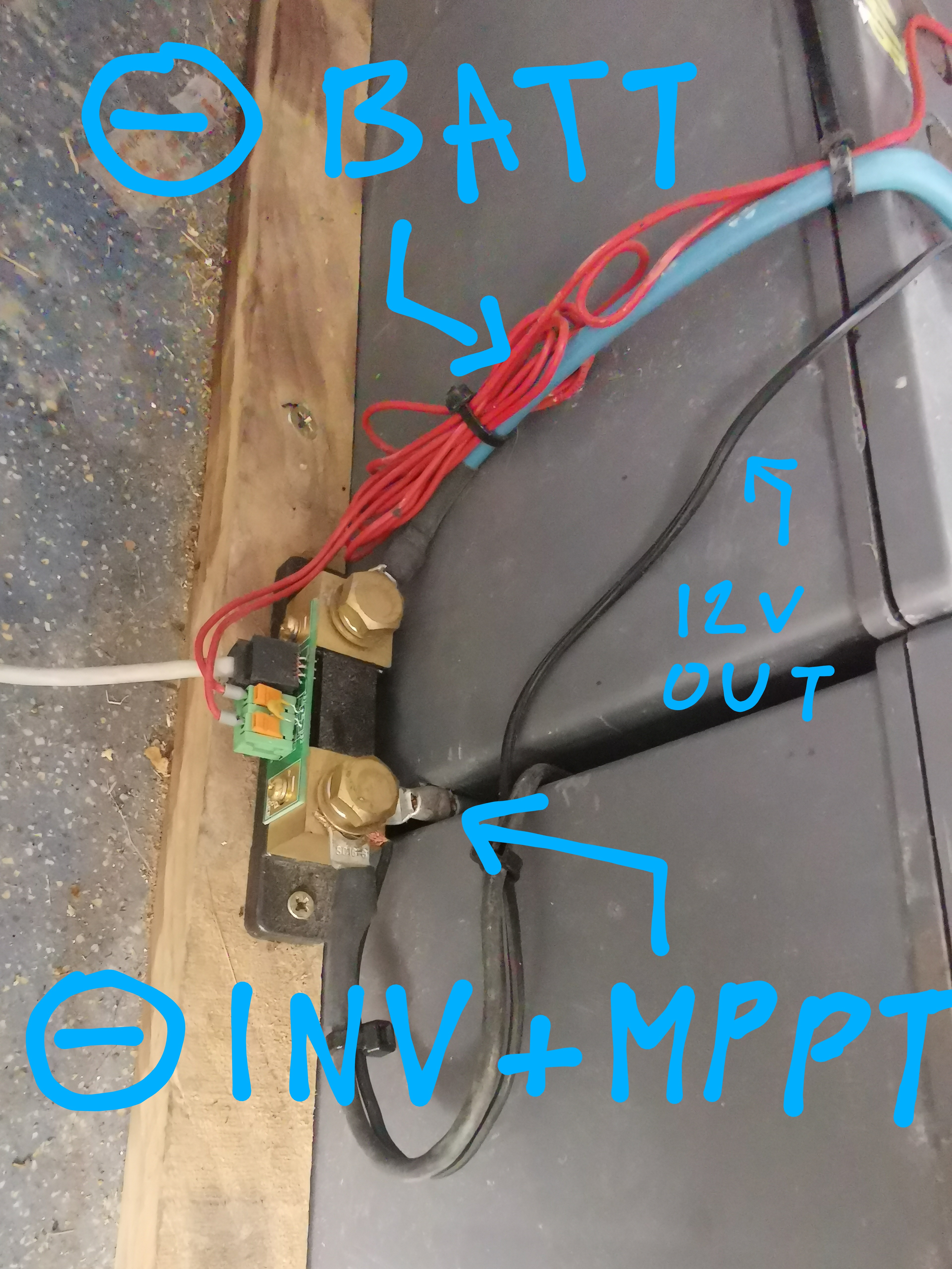
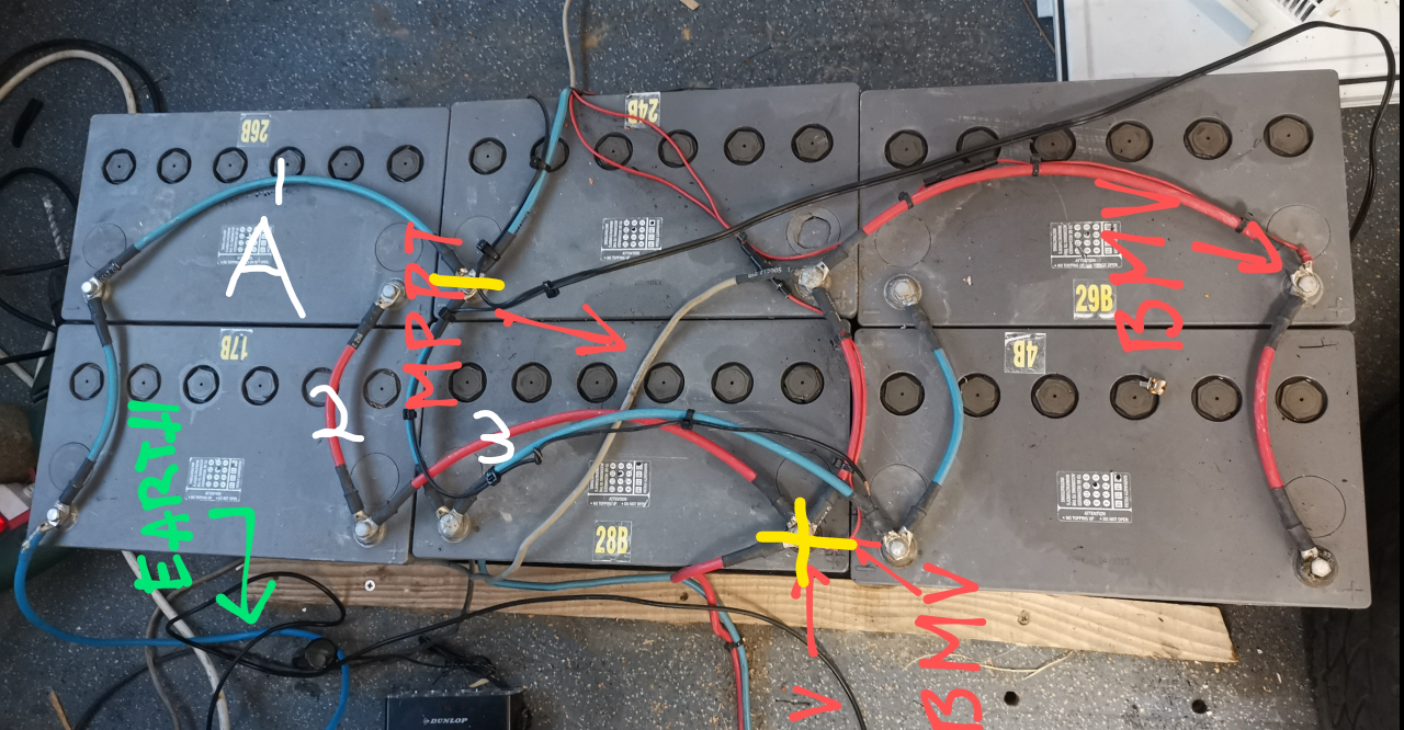
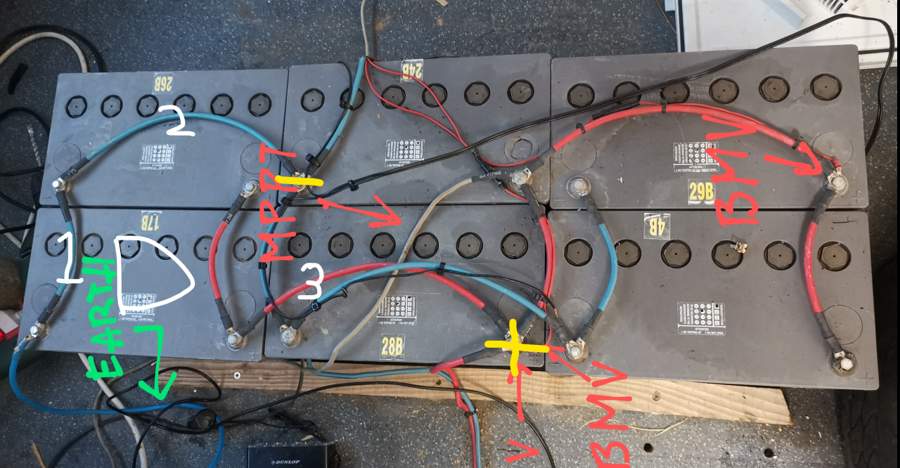
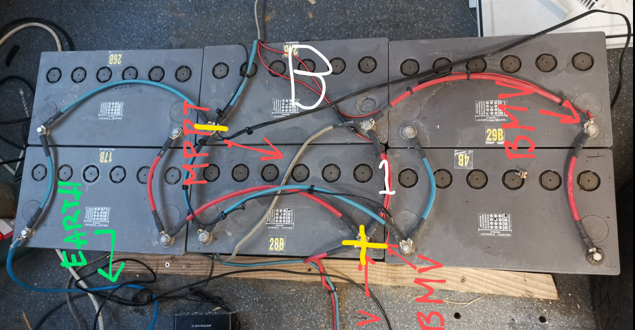
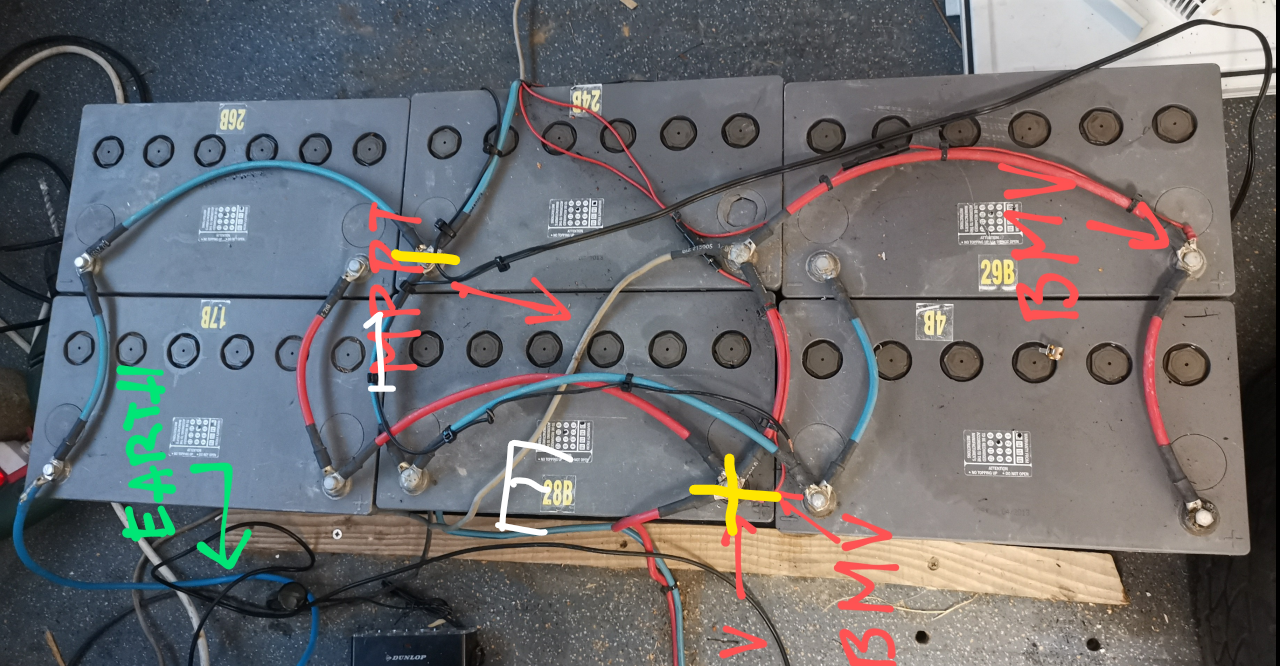
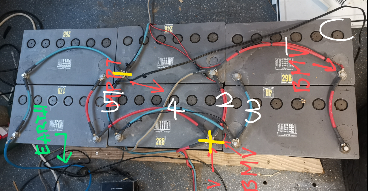
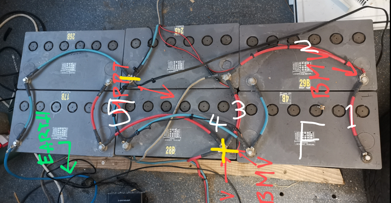
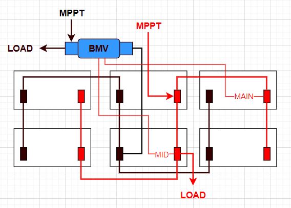
Or perhaps my cabling is wrong, unlikely but possible.

BMV Battery MonitorPhoenix Inverter
2 |3000

Up to 8 attachments (including images) can be used with a maximum of 190.8 MiB each and 286.6 MiB total.

7 Answers
renz avatar image
renz answered ·

The culprit was indeed the circuit breaker. Thanks @klim8skeptic

The ABB works normally and it was only 10 Euros more than the cheap one, and on top it's dual contact. Voltage is now constant under 500w all round.

As a summary, there was nothing really bad with the batteries, they are old but they work fine still. I'd rather keep them until they are shredded since the pollution that relates to transport of lead acid batteries is not ethical so far as they have to ship them overseas to recycle them.


2 |3000

Up to 8 attachments (including images) can be used with a maximum of 190.8 MiB each and 286.6 MiB total.

klim8skeptic avatar image
klim8skeptic answered ·

Or perhaps my cabling is wrong, unlikely but possible

Perhaps a picture of your system would help?

2 |3000

Up to 8 attachments (including images) can be used with a maximum of 190.8 MiB each and 286.6 MiB total.

renz avatar image
renz answered ·

Here you go, I can actually see that the inverter is connected to a different battery vs the MPPT, that's a variation I have added to even the energy spread, but the BMV point 1 is connected onto the exact same one, so I still don't see how I get this issue. I'm a bit of a noob in wiring though.

img-20220916-1101352.jpgimg-20220916-110144.jpgimg-20220916-1101562.jpg

img-20220916-1103012.jpg

img-20220916-1103132.jpgimg-20220916-1103212.jpg


1 comment
2 |3000

Up to 8 attachments (including images) can be used with a maximum of 190.8 MiB each and 286.6 MiB total.

klim8skeptic avatar image klim8skeptic ♦ commented ·
I have made most mistakes, pls interpret this as constructive criticism.


Your choice of inverter circuit breaker and it's location is bad. I used a similar CB and they are just garbage, tripping below current rating and voltage drop. Breaker should be located close to the battery, to protect the cable running to the inverter.

Your cross diagonal battery wiring is wrong. The center batteries are taking most of the charge, and most of the load.

Your batteries are circa 2013. One of them has a dodgy looking battery post. They are at, or over their life expectancy. Time to start looking at replacements.

After you have replaced the CB though.

0 Likes 0 ·
renz avatar image
renz answered ·

Thanks for your reply @klim8skeptic

I will:

  1. Rewire the battery bank as you might are certainly right about the incorrect cross diagonal sequence

  2. Test them again individually

  3. check the voltage on the inverter's terminals

Then will go from there.


6 comments
2 |3000

Up to 8 attachments (including images) can be used with a maximum of 190.8 MiB each and 286.6 MiB total.

Matthias Lange - DE avatar image Matthias Lange - DE ♦ commented ·

You should take a look into the Wiring-Unlimited Book:
https://www.victronenergy.com/upload/documents/Wiring-Unlimited-EN.pdf
(Chapter 3)

If you can rotate the batteries 90° you have it exactly like in the book and you can make a much cleaner wiring.

The "earth" wire also have to be at the shunt, not at the battery.

1 Like 1 ·
renz avatar image renz Matthias Lange - DE ♦ commented ·

I still don't get the difference

Victron's manual

capture.jpg

My bank

capture.jpg

0 Likes 0 ·
klim8skeptic avatar image klim8skeptic ♦ renz commented ·

I still don't get the difference

The loads and charge points have to be at the same point of the battery bank.

Here is how I have looked at it.

You have 6 batteries hooked up. To share the same load, each battery has to have the same length current path, both in terms of cable length, but also the number of cables. You have to look at both the positive and negative cabling.

What I did was to look at each battery, and count the total number of links each battery needs to run through to reach the final load / charge point.

How to correctly interconnect multiple batteries to form one larger bank.

0 Likes 0 ·
renz avatar image renz klim8skeptic ♦ commented ·

Gday @klim8skeptic ,

I know smartgauge.co.uk very well, this is what gave me the idea of cross diagonal wiring a few years ago. I've been designing battery banks using this method for about 3 years now and know the cable length path issue.

I am not an electrician though, just a designer. This very system is mounted on my personal camper van and I believe that there would be an issue with the circuit breaker, I will look into it.

Now, the battery wiring, as I said, it's unlikely that the wiring would be incorrect, I do not see any cable length different from one side to the other. I know well the internal resistance issues you can get with different cable lengths on the parallel circuit.

I do not see why the charging and loading points must be different as according thos cross parallel, there are 2 bipolar points that can be used.

Please correct me if I'm wrong.

0 Likes 0 ·
klim8skeptic avatar image klim8skeptic ♦ renz commented ·

I like to count battery interconnects.

Battery A and D have 3 interconnects.

6p-batt-a.png

6p-batt-d.png

It looks like battery B and E only have 1 interconnect each.

6p-batt-b.png

6p-batt-e.png

And battery C and F have 5 interconnects each.

6p-batt-c.png

6p-batt-f.png

Time for some new batteries.

0 Likes 0 ·
6p-batt-a.png (1.5 MiB)
6p-batt-d.png (1.5 MiB)
6p-batt-b.png (1.5 MiB)
6p-batt-e.png (1.5 MiB)
6p-batt-c.png (1.5 MiB)
6p-batt-f.png (1.5 MiB)
renz avatar image renz klim8skeptic ♦ commented ·
Apologies for the delay answering. I will get back here once I have tested the voltage after the CB. Thanks for the time you have spent here @klim8skeptic I will be back shortly.
0 Likes 0 ·
renz avatar image
renz answered ·

Here is a drawing of how it is wired on the existing system

capture.jpg

Please let me know if either this drawing is incorrect or if there is something incorrect on it.


capture.jpg (44.4 KiB)
2 |3000

Up to 8 attachments (including images) can be used with a maximum of 190.8 MiB each and 286.6 MiB total.

renz avatar image
renz answered ·

The cheap monkey circuit breaker stopped delivering current completely, I'm ordering a better one. Thing is, most automotive type circuit breakers, those black ones, very often go faulty. In my stationary system, I always use ex telecom breakers because they just work fine, never had an issue with those. I ordered a bipolar ABB to replace it.

2 |3000

Up to 8 attachments (including images) can be used with a maximum of 190.8 MiB each and 286.6 MiB total.

renz avatar image
renz answered ·

The culprit was indeed the circuit breaker. Thanks @klim8skeptic

The ABB works normally and it was only 10 Euros more than the cheap one, and on top it's dual contact. Voltage is now constant under 500w all round.


2 |3000

Up to 8 attachments (including images) can be used with a maximum of 190.8 MiB each and 286.6 MiB total.