question

kw4np avatar image
kw4np asked

Cerbo GX Calculate Battery SOC from Multiple Shunts/Inverters

Is it possible to keep track of the system SOC using both VE.Bus/VE.Direct inverters and chargers and a SmartShunt connected to a Cerbo GX? No current is flowing in the system without going through either an inverter or a shunt (but not both), and the Cerbo has all of that information.

The manual is a bit vague but mentions that using a SmartShunt as a DC Energy Meter in DC System mode has an effect on some calculations, much like the calculation that the Cerbo makes when showing the DC System voltage in a system with a main battery shunt.

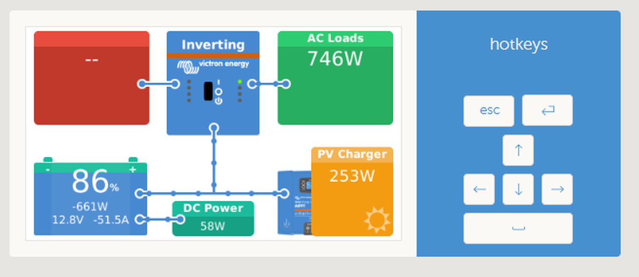
"When configured as type “DC System”, the GX does more than just recording and visualisation:
1. the power shown in the DC system box is the sum of power reported by all SmartShunts configured as such. Allowing multiple meters is done to accommodate for example a catamaran, so you can measure the DC Systems on Port hull and on Starboard hull.

2. the DC System Current is being compensated for when setting DVCC charge current limits to Multis, Quattros and Solar Chargers. For example when a load of 50A is being measured, and CCL by the battery is 25A, the limit given to the Multis & Solar Chargers is 75A. An improvement for systems with significant DC loads such as Yachts, Coaches and RVs."

The configuration in this case would not be Batteries>SmartShunt>Inverters/Loads/Chargers but rather Batteries>Inverters and Batteries>SmartShunt>Loads/Chargers

I've been told that this is not possible, if that is indeed the case how would I go about making a feature request? It seems like a very useful feature especially for large systems.

cerbo gxSmartShuntSOC
4 comments
2 |3000

Up to 8 attachments (including images) can be used with a maximum of 190.8 MiB each and 286.6 MiB total.

kw4np avatar image kw4np commented ·

To @Mike Dorsett , @klim8skeptic , @Guy Stewart (Victron Community Manager) , and anyone else who is asking (legitimately) why I don't just use the shunt as a battery monitor, I have a few reasons:

1) A single bus bar for batteries and inverters seems safer and more efficient as well as a simpler design with less to go wrong.

2) Bus bars cost money, take up space, and take time to install.

3) DC Loads may not be accounted for, unless a SmartShunt or BMV-712 is installed, and correctly configures as a DC load monitor. For example, without the DC load monitor a configured maximum charge current of 50 Amps, and DC Loads drawing 20 Amps, the battery will be charged with 30 Amps. Not with the full allowed 50 Amps. With the SmartShunt configured as a DC load monitor, maximum charge current configured at 50 Amps, and DC system shunt reports a draw of 25 Amps. Then the chargers are set to charge with 50 + 25 = 75 Amps. (straight from GX manual regarding DVCC, which is required by ESS)

And it seems really easy to sum up the energy going in and out of the battery, just like the DC System value would be calculated if the shunt was a battery monitor.

illustration.png

0 Likes 0 ·
illustration.png (55.6 KiB)
klim8skeptic avatar image klim8skeptic ♦ kw4np commented ·
Do you have any non Victron DC chargers?


Wind turbine? Other solar chargers? Water turbine?

0 Likes 0 ·
kw4np avatar image kw4np klim8skeptic ♦ commented ·
@klim8skeptic , Yes, a bunch of MPPTs, plus a DC freezer.
0 Likes 0 ·
kw4np avatar image kw4np kw4np commented ·
DVCC seems to be taking my solar charge into account while charging. So at least that part is working. I only need SOC to be able to use ESS.
0 Likes 0 ·
4 Answers
kw4np avatar image
kw4np answered ·

Apparently the "Solar Charger" mode in the SmartShunt calculates both DVCC and SOC values for the entire battery system. Seems like it's publishing the values on VE.Bus for the internal battery monitor on the Quattros, but hard to tell for sure. @Guy Stewart (Victron Community Manager) , it would be really helpful if this were in the manual! So if you're like me and mostly trying to track solar chargers and a few loads, "Solar Charger" mode seems to work properly.

2 |3000

Up to 8 attachments (including images) can be used with a maximum of 190.8 MiB each and 286.6 MiB total.

Mike Dorsett avatar image
Mike Dorsett answered ·

Why do you not connect your inverter and MPPT chargers through the shunt? It is more accurate at measuring current. DC current could then be derived (as expected) by subtracting the inverter and charger current from the shunt value, or by adding an auxiliary shunt to the system.

1 comment
2 |3000

Up to 8 attachments (including images) can be used with a maximum of 190.8 MiB each and 286.6 MiB total.

kw4np avatar image kw4np commented ·

@Mike Dorsett I wanted to use a common bus for all my inverters and batteries and connect the few loads and chargers to the SmartShunt. As far as accuracy goes, it seems like the total system accuracy might be better if used as a battery monitor but DC System accuracy would be the same or worse. It's possible to switch to use it as a battery monitor, but the wiring is pretty tight right now.

0 Likes 0 ·
klim8skeptic avatar image
klim8skeptic answered ·

I am struggling to visualize what is wrong with the existing setup.

vrm-snap.png

remote.png

Sure the DC power figures are calculated, but are close/fast enough for most purposes.

All DC current going through the shunt gives very accurate measured SOC figures.


remote.png (133.1 KiB)
vrm-snap.png (62.1 KiB)
6 comments
2 |3000

Up to 8 attachments (including images) can be used with a maximum of 190.8 MiB each and 286.6 MiB total.

kw4np avatar image kw4np commented ·

@klim8skeptic , I'm not sure what setup you are using. I wanted to use a common bus for all my inverters and batteries and connect the few loads and chargers to the SmartShunt.

0 Likes 0 ·
klim8skeptic avatar image klim8skeptic ♦ kw4np commented ·

I am using the conventional setup. A busbar for both positive and negative, with the negative bus bar at the yellow circled location.

bmv.png

All system wiring then returns (originates?) via the 2 busbars.

0 Likes 0 ·
bmv.png (146.8 KiB)
kw4np avatar image kw4np klim8skeptic ♦ commented ·
@klim8skeptic , the difference with my system is that I have 4 batteries and 3 Quattros and they're all on one (negative) bus bar. The SmartShunt battery terminal is attached to that bus bar as well. The solar charger and a few small DC loads are attached to the system terminal.

I did it that way to:

1. Avoid extra connections and losses (even the SmartShunt is by definition a large resistor).

2. Avoid having to buy or make another bus bar for the batteries.


0 Likes 0 ·
kw4np avatar image kw4np kw4np commented ·

I'm using it like in this diagram except with a bus bar in place of D.

0 Likes 0 ·
klim8skeptic avatar image klim8skeptic ♦ kw4np commented ·
A 50mV/500a shunt has the resistance of 100 micro ohms??


What is the resistance of your added bus and extra cable/crimps before the shunt??

0 Likes 0 ·
kw4np avatar image kw4np klim8skeptic ♦ commented ·
@klim8skeptic , I'm not sure what the added resistance would be. I'd have to make another bus and wire it in. The resistance matters as I'm potentially running up to 500 amps through the bus bar.

If the measurement from the Quattros is accurate, it seems like it's better design to use a single bus bar. That eliminates several connections and makes the installation simpler.


0 Likes 0 ·
Alexandra avatar image
Alexandra answered ·

You make a negative bus bar for all the inverters and mppts and a negative bus bar for the battery bank with the shunt inbetween the two.

It is the only way to get accurate SOC for one bank of batteries, unless you have CAN managed batteries, which is usually the case with much larger systems.

1 comment
2 |3000

Up to 8 attachments (including images) can be used with a maximum of 190.8 MiB each and 286.6 MiB total.

kw4np avatar image kw4np commented ·

@Alexandra , that's not the question, I know how to use the SmartShunt as a battery monitor but for reasons above I want to use it as an energy meter. The SOC would be accurate enough for me if it was possible to simply sum the two values here, which is actually being done for DVCC.

illustration.png
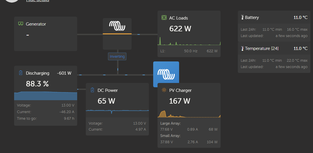
Unfortunately I don't have CAN managed batteries, they are very large but sourced in Africa. I may eventually replace the BMS but for the moment I just want to use the sum of VE.Bus and the energy meter to calculate total current flow in and out of the battery, which will give me a fairly accurate SOC. Do you know of any way to do that?


0 Likes 0 ·
illustration.png (55.6 KiB)