question

Nick Roberts avatar image
Nick Roberts asked

dbus Serial Battery driver - pull State Of Charge value from Victron Smart Shunt instead

Hi All,


I have a question surrounding the JK BMS Driver for Venus, Victron Smart shunt and Battery charging / management.


My configuration:

  • Victron Multiplus II 5000VA
  • Victron Solar Charge Controller 250/100
  • 48v setup 3.2v LiFeP04 (x 16 cells)
  • JK BMS 150A (connected to Venus via RS485 to USB)
  • Victron Smart Shunt
  • Cerbo GX


So like many, I've been running a JK BMS utilising the driver that Louis van der Walt has written to pull data into Venus OS and allow the BMS to control the output of the Solar charge controller

(see https://community.victronenergy.com/questions/76159/victron-venusos-driver-for-serial-connected-bms-av.html)


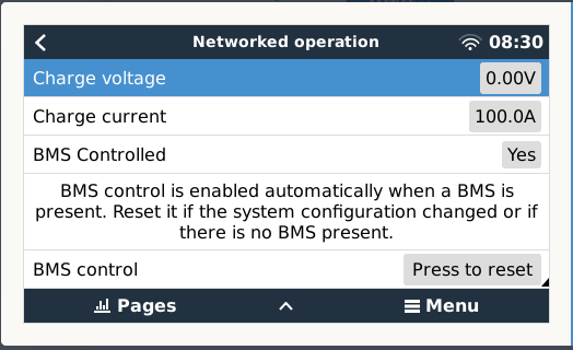
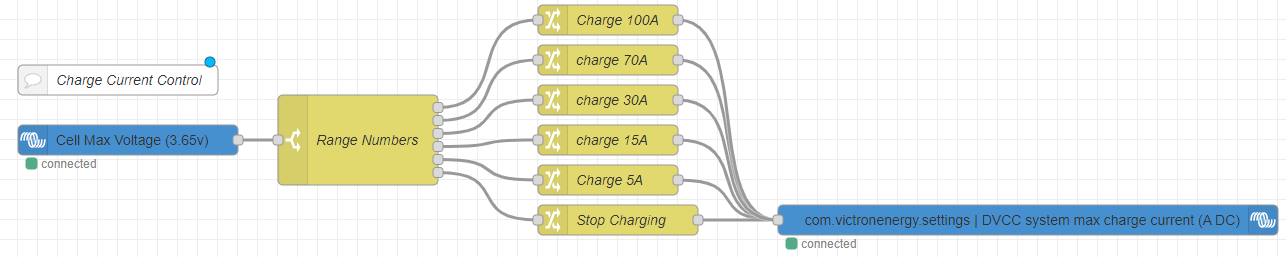
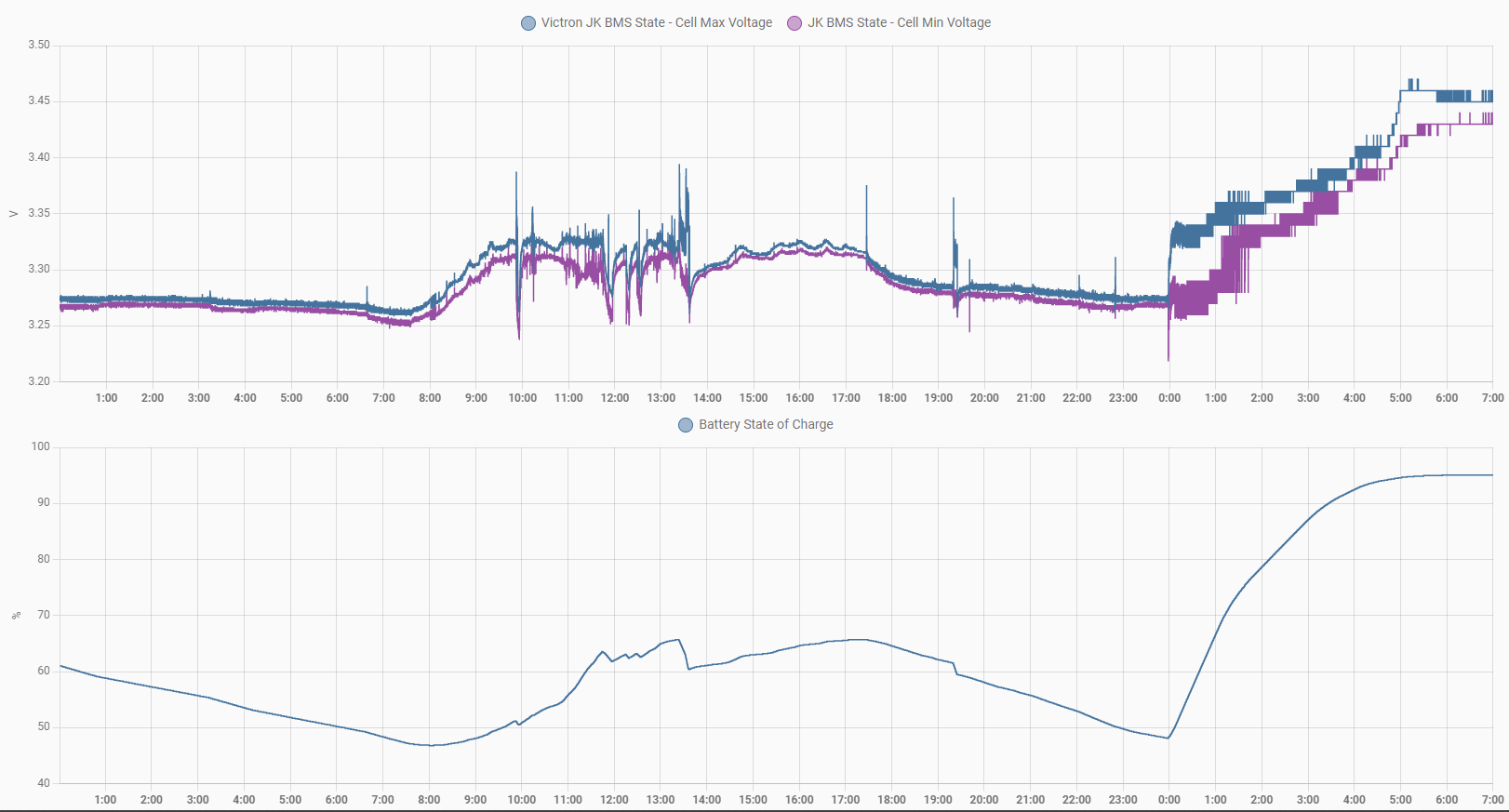
The system (for the most) part works great, however where I have been seeing faults is at the end of charge, where the Charge current control management (CCCM) feature of the driver starts lowering current as the state of charge nears 100%. The issue I have is that the state of charge reported back by the JK BMS is usually off by at least 3%, sometimes as many as 10% compared to my Victron smart shunt. This results in the current not being lowered when it counts and pushes the batteries close to being over-charged.


I was wondering if it would be possible to modify the driver to pull the State of charge from the victron smart shunt instead of the BMS?

dbus - com.victronenergy.battery Address 266


I believe the JK BMS state of charge value is obtained in the jkbms.py script, line 95

self.soc = unpack_from('>B', self.get_data(status_data, b'\x85', offset, 1))[0]

(https://github.com/Louisvdw/dbus-serialbattery/blob/master/etc/dbus-serialbattery/jkbms.py)


But I wouldn't have a clue on how to insert the Smart shunt SOC figure into that slot.

If anybody with a bit more experience is able to help it would be much appreciated!


Nick R


MPPT Controllerscerbo gxVenus OSBMS
2 |3000

Up to 8 attachments (including images) can be used with a maximum of 190.8 MiB each and 286.6 MiB total.

6 Answers
Mike Dorsett avatar image
Mike Dorsett answered ·

you actually need to change the D-bus commands for charge current to be based on Max cell voltage, rather than SOC. SOC is a computed rather than measured parameter, and so is always less accurate than the cell voltages. Louis' code can be easily edited to do this.

1 comment
2 |3000

Up to 8 attachments (including images) can be used with a maximum of 190.8 MiB each and 286.6 MiB total.

Nick Roberts avatar image Nick Roberts commented ·

You describe the ideal set up, I tried implementing a control loop like this in NodeRED but unfortunately as far as I can tell the solar charge controller current isn't set on the dbus - the only writable address is 744 (Solar charger on/off)

I'm not sure how it does it, but the BMS drives the Solar Charge controller, I haven't found out where that set point lives in order to implement my own control loop

1662017433268.png


A modification to Louis's code do drive charge current based on Cell Max voltage would be a better option than relying on the SOC figure the JK calculates. (It is not perfect still as the JK's voltage measurement drifts from the smart shunt's over several days, but that's another quirk to work out)


Modifying the code however that is beyond my capability - From what I can see, the CCCM control lives in battery.py from line 115

https://github.com/Louisvdw/dbus-serialbattery/blob/master/etc/dbus-serialbattery/battery.py#L115

The cell max voltage also lives in battery.py from what I can see.


I have tinkered with it and tried the following:

1662022386569.png


However, it bricks the driver and shows up as disconnected in venus OS.


Any ideas on how to implement this properly?


Cheers,

Nick R


0 Likes 0 ·
1662017433268.png (32.0 KiB)
johanndo avatar image
johanndo answered ·

I would stop the service and run the driver from the shell to see where it crashes, usually a typo or indentation fault. You can also read the log in /data/log/[drivername]/current

2 |3000

Up to 8 attachments (including images) can be used with a maximum of 190.8 MiB each and 286.6 MiB total.

Mike Dorsett avatar image
Mike Dorsett answered ·

I'm not sure that "self.cell_max_voltage" is visible in this part of the code.

you would need to iterate through self.cells_v list to get the max voltage. Otherwise add a global variable to the get_max_cell function and use that to get the max cell voltage.

(It's been about a year since I last looked at this code...)


2 |3000

Up to 8 attachments (including images) can be used with a maximum of 190.8 MiB each and 286.6 MiB total.

pau1phi11ips avatar image
pau1phi11ips answered ·

I think this might be more appropriate to discuss on GitHub tbh

https://github.com/Louisvdw/dbus-serialbattery/issues

2 |3000

Up to 8 attachments (including images) can be used with a maximum of 190.8 MiB each and 286.6 MiB total.

larsea-dk avatar image
larsea-dk answered ·

Hi Nick

Very good idea, any progress or solution??

I'm considering having Victron controlling everything, but still want to be able to see battery measurements in the VRM from the JK BMS. I thought only the utily-file was to be edited, but I have much still to learn. I expirenced that I had very much sun yesterday and since grid feed in was activated, it just continued overcharging my battery beyond the settings I wrote into the BMS driver (Utils-file). I wasn't home and in a meeting, so had to tell the wife she should turn the battery cut-off switch :-/ Not funny. It might be due to I updated to Large venus OS to go into node.red and the setting for Battery monitor was set to "automatic".


BR,

Lars

3 comments
2 |3000

Up to 8 attachments (including images) can be used with a maximum of 190.8 MiB each and 286.6 MiB total.

bonzai avatar image bonzai commented ·
Hello,

which version of the driver are you using? in the new version from 0.14.3 it is possible to charge the accu via the number of volts of the cells, independent of the soc. I myself still use this version of WaldemarFech (https://github.com/WaldemarFech/dbus-serialbattery). because this works fine for me. I think Louis is optimizing the driver so that it can be configured via a config.ini, but I don't think it's in the final version yet. There is also a version that is supposed to work via Bluetooth, which I haven't tried yet either.
0 Likes 0 ·
larsea-dk avatar image larsea-dk bonzai commented ·

it is actually the 0.14.3. I just installed it to get NodeRed, but did not check whats new. I'm not strong in programming, but is there a guide somewhere to what can be adjusted or is it only the # texting available? As I understand, only adjustment are made in the utils.py. Should it be set to False for the CCCM?


# Charge current control management enable (True/False).

CCCM_SOC_ENABLE = "True" == config["DEFAULT"]["CCCM_SOC_ENABLE"]
# Discharge current control management enable (True/False).
DCCM_SOC_ENABLE = "True" == config["DEFAULT"]["DCCM_SOC_ENABLE"]

0 Likes 0 ·
bonzai avatar image bonzai larsea-dk commented ·

no, not any more in the utils.py. there must be a default_config.ini.

there you can choise the LINEAR_LIMITATION_ENABLE = True.

The Linear mode make it over the Voltage of the cells. if you take "False" you have a hard limit over soc.


For me this version is also new, there fore i took the waldemar_frech (here you have to edit the utils.py, becaus its a older version) but it runs out of the box :-)


I wait until Louis make a final releas, becaus there were a lot of changes.


0 Likes 0 ·
larsea-dk avatar image
larsea-dk answered ·

Hi Nick


Watch this...I think this actually goes a bit in the right direction, but it seems like cell voltages might not be considered anymore...but still visible and recorded. And then it might be possible to do something with some NodeRed coding?

https://www.youtube.com/watch?v=tSi-VdI3Ah4

2 comments
2 |3000

Up to 8 attachments (including images) can be used with a maximum of 190.8 MiB each and 286.6 MiB total.

Nick Roberts avatar image Nick Roberts commented ·

I went down this route in the end, I disabled the CCCM and CVCM and ended up writing all the control in NodeRED.

Rather than drive the charge current limit based on SOC (as this is not always accurate), I based the control on the battery cell max voltage (the highest individual cell voltage in the pack)

Since you can pull the BMS data via the Battery Monitor node and write the DVCC limit, this was an simple but effective way of dropping the charge current as the pack neared full charge.

1678094672093.png

It has been in service for a couple months now and has been working reliably!


Below is a graph showing the min cell voltage vs max cell voltage and SOC % and how closely they track in use and during charging. While the graph looks a bit gappy during balancing, the cell variance is only 4mV but ordinarily sits around 1mV .


Well worth looking into if you're also having charge / balance issues.


Cheers all for your input on this


charge-cycle.png

0 Likes 0 ·
1678094672093.png (51.0 KiB)
charge-cycle.png (94.6 KiB)
larsea-dk avatar image larsea-dk Nick Roberts commented ·
Hi Nick


Could it be possible to export that flow and pm it to me. Would be funny to se how it works… of course in debug mode. That is really interesting and it looks actually to work quite well. But this is probably not working when feedin excess is activated i guees, but can be extended to do so. Isn’t this a bit similar to what louisvdw also has made in the driver, where you can choose charge level based on cell voltages rather than the not very stable SOC.
1 Like 1 ·