question

cycl0ne avatar image
cycl0ne asked

MultiPlus II Setup with PV -> Critical Loads

My Setup is as follows with 3 Multiplus II - 8000 for 400v 3Phase:

xmgtop5.jpg

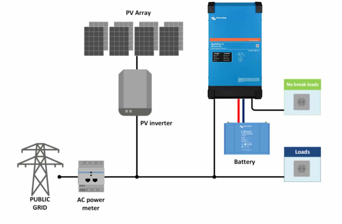
The PV Inverter is on the Net side then the Cable goes into the 3 Multiplus Input and then Output 2 goes into the house.

Now my question: In the VRM Portal it looks like this:

vrm1.png

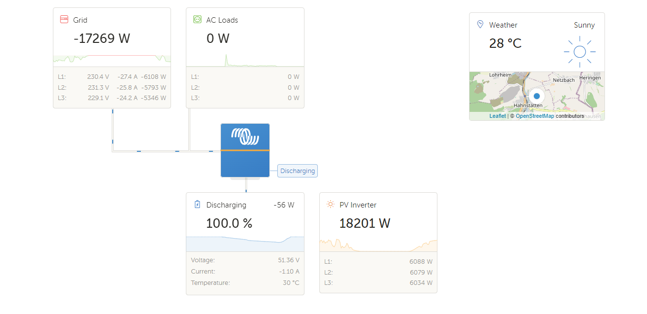
if i enable the switch AC-Output in ESS it looks like this:

vrm2.png


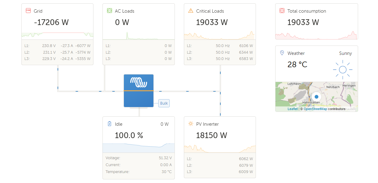
Why is critical loads in plus and so high when the Grid is negative? Why is load at 0? Is it because of the used Meter ET340? I read something about it giving wrong data in a single phase system?


Thanks!

Cheers

C.

Multiplus-IIVRM
xmgtop5.jpg (19.2 KiB)
vrm1.png (75.6 KiB)
vrm2.png (85.3 KiB)
2 comments
2 |3000

Up to 8 attachments (including images) can be used with a maximum of 190.8 MiB each and 286.6 MiB total.

lifeingalicia avatar image lifeingalicia commented ·
check cabling L1 - L3 as well as coms cabling - need to be in sequence Victrom assumes L1 on master (I think)
0 Likes 0 ·
cycl0ne avatar image cycl0ne lifeingalicia commented ·

All checked. L1, L2 and L3 are on the Correct Multiplus, COMs are also correct. Its strange. What i will now try. I will use the Output 1, which is the one which is supplied even when net has gone down.

It seems the PV in the VRM Portal is just added to the crit loads instead substracted.

0 Likes 0 ·
2 Answers
marekp avatar image
marekp answered ·

Is this PV inverter properly position in the GX?

screen-shot-2022-08-29-at-21222-am.png


2 comments
2 |3000

Up to 8 attachments (including images) can be used with a maximum of 190.8 MiB each and 286.6 MiB total.

cycl0ne avatar image cycl0ne commented ·

Thanks. Could be. It says in that Menu: AC OUTPUT.

But if i enter the Menu, it says:

AC Input 1
AC Input 2
AC Output

But my Multiplus has:

Output 1
Output 2
Input 1

So, as shown in the picture im in the Input. So what could be the correct setting?

- Update

i just switched to Input 1 and now everything looks correct in VRM Portal. Wonder what happens if i switch to input 2 which is non existent on the multi.

0 Likes 0 ·
cycl0ne avatar image cycl0ne cycl0ne commented ·
That was it! Putting it to Input 2 (which i dont have in the Multi II) doesnt work. Input 1 works perfectly. Now all values are correct in VRM !! THANK YOU VERY MUCH !!!!!
0 Likes 0 ·
mildredryan avatar image
mildredryan answered ·

The MultiPlus-II will use data from the external AC current sensor (must be ordered separately) or power meter to optimise selfconsumption and, if required, to prevent grid feed. In case of a power outage, the MultiPlus-II will continue to supply the critical loads. Monkey

1 comment
2 |3000

Up to 8 attachments (including images) can be used with a maximum of 190.8 MiB each and 286.6 MiB total.

cycl0ne avatar image cycl0ne commented ·
Yes, im using the ET340 from Victron.
0 Likes 0 ·