question

murphy-r avatar image
murphy-r asked

New Lithium Smart Bank Commissioning. Watts Charged Lower Then Expected

Hello,

Making progress on a new installation of Multiplus 12/3000 + Lynx BMS + Lithium Smart Batteries (4).

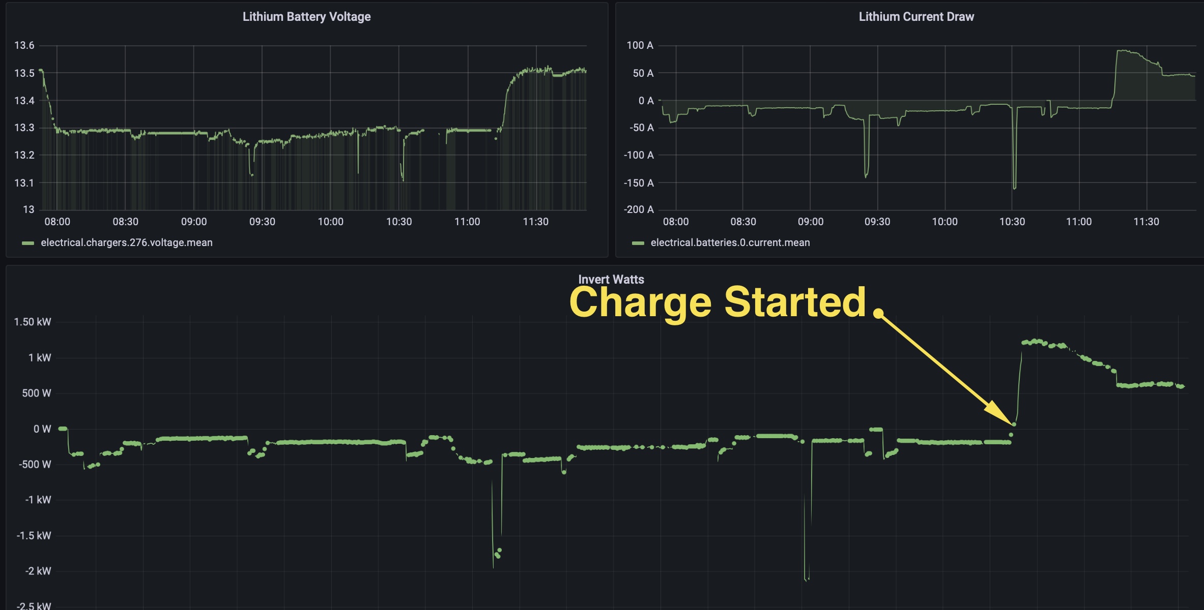
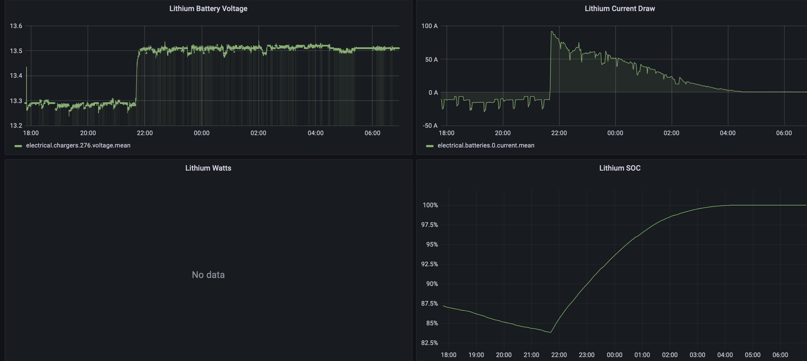
I did my first set of load testing and got the bank from full charge down to 80%. When I provided AC shore power back to the Multiplus I only say about 1.2kW of charge current which then tapered down. See graph below showing the start of inverter test and back to charge.

The Multiplus is set to max 30A AC1 inlet

The Lynx BMS is set for

  • Battery Capacity 330A
  • # of Batteries in Parallel 4

I was expecting the Multiplus to have a larger charge current to the battery bank.

Anyone know what the max watts a Multiplus 12/3000 can generate on the charging side? The data sheet was unclear.

Could this be something the BMS is dictating through DCVV because I thought it only set the voltage settings.

Cheers,

-R

inverter-bank-test-run.jpg

BMSsmart lithium
2 |3000

Up to 8 attachments (including images) can be used with a maximum of 190.8 MiB each and 286.6 MiB total.

8 Answers
Matthias Lange - DE avatar image
Matthias Lange - DE answered ·

The 12V 3000VA MultiPlus has a charging current of max 120A -> around 1500W.

If I remember correctly the default current is set to 80 or 90A.

2 |3000

Up to 8 attachments (including images) can be used with a maximum of 190.8 MiB each and 286.6 MiB total.

Stefanie (Victron Energy Staff) avatar image
Stefanie (Victron Energy Staff) answered ·

Hi @murphy_r,

  1. If you have 4 batteries, each 12.8V/330Ah and in parallel configuration, the battery capacity in the Lynx Smart BMS settings must be 4 x 330Ah = 1320Ah.
  2. From the Grafana graph it looks like the batteries are in "float", which means the charge voltage limit is 13.5V. The charger ramped up to full charge current (I remember from your other thread it was set to 90A) initially and as soon as voltage increased, the current started tapering down.

Everything looks normal. Nothing to worry about.


4 comments
2 |3000

Up to 8 attachments (including images) can be used with a maximum of 190.8 MiB each and 286.6 MiB total.

eliott avatar image eliott commented ·
Hi! Can I please ask what difference does the number of batteries and the capacity setting make? I usually enter 1 battery and the total Ah of the system. Once I did as it should be done and the shunt did not display the correct SOC, so I changed back to the 1 x total Ah
0 Likes 0 ·
Stefanie (Victron Energy Staff) avatar image Stefanie (Victron Energy Staff) ♦♦ eliott commented ·

Hi @eliott,

AFAIK this setting is used to determine certain parameters for balancing, SOC etc. But I'll come back to that as soon as I know the exact details.

It is to be expected that the SOC will display incorrect values after changing the battery capacity. Even a BMV or SmartShunt does this. After next full charge cycle and syncing it should show correct values.

0 Likes 0 ·
eliott avatar image eliott Stefanie (Victron Energy Staff) ♦♦ commented ·
Thanks, it would be good to know, because we are many installations with the 1xTotal Ah setting. I've checked the documentation but there was no info
0 Likes 0 ·
Stefanie (Victron Energy Staff) avatar image Stefanie (Victron Energy Staff) ♦♦ eliott commented ·

Just to confirm what I wrote yesterday.

Capacity is used for SoC and the number of parallel batteries is used for the built in battery balancing algorithm. Basically a wrong number of batteries in parallel results in a wrong (internal) threshold which in return can result in a wrong balancing detection from the BMS.

0 Likes 0 ·
murphy-r avatar image
murphy-r answered ·

Thanks Matthias and Stephanie! Really appreciate the insight.

I had the exact question on the battery capacity field whether that was the total bank or per battery.

I update the BMS with the settings and went back into the Multiplus and changed the default 90A to the max 120A.

I will switch over back to Inverter and run the batteries through a discharge / charge cycle.

Cheers,

Robert

2 |3000

Up to 8 attachments (including images) can be used with a maximum of 190.8 MiB each and 286.6 MiB total.

murphy-r avatar image
murphy-r answered ·

Did some additional research and found out that my Multiplus has a DC max current charge setting on the dip switches in the device. The default was hard coded at 75% and I changed it to 100% (DS 3,4). Will try another test on the inverter bank in the next few days and see if I can bump up the watt charging rate.

1 comment
2 |3000

Up to 8 attachments (including images) can be used with a maximum of 190.8 MiB each and 286.6 MiB total.

Matthias Lange - DE avatar image Matthias Lange - DE ♦ commented ·
If you already use VE.config to configure the MultiPlus, you don't need to change the DIP switch settings. The VE.config settings overwrite/overrule the DIP settings.
0 Likes 0 ·
Stefanie (Victron Energy Staff) avatar image
Stefanie (Victron Energy Staff) answered ·

@murphy_r

I'm not sure what exactly you're asking.

Dip switches 8, 7 and 6 have nothing to do with charging current. They are supposed to set the input current limit. See your MultiPlus manual section 5.5.1.1.

I suggest looking for DS 4 and 3. This works in increments of 25%, so very inaccurate. And when you have 'WeakAC' enabled, the max. charge current ist reduced from 100% down to 80%. See the MultiPlus manual 5.5.1.3

It's much easier to set the max. charge current to 120A using a PC together with MK3 to USB interface and VEConifgure or simply by using a PC and our VRM Remote VEConfigure feature and then limit the charge current via the DVCC menu of your GX device from 0A up to 120A.

2 |3000

Up to 8 attachments (including images) can be used with a maximum of 190.8 MiB each and 286.6 MiB total.

murphy-r avatar image
murphy-r answered ·

Thanks Stefanie,

I corrected my earlier post on the dip switches to reflect the correct value. Can the VE.CAN from the GX override the dipswitch setting?

I went into my GX -> Settings -> DCVV -> and the limit charge current is OFF. Can I assume correctly that it will now take the hardware dipswitch setting.

Appreciate the help and hope your enjoying boat life.

-R

1 comment
2 |3000

Up to 8 attachments (including images) can be used with a maximum of 190.8 MiB each and 286.6 MiB total.

You're welcome!

See the comment from @Matthias Lange - DE further above. VEConfig settings will overwrite dip switch settings and hopefully DVCC does the same. But I haven't tried that myself yet. On all multi's I leave the dip switches at their default settings. You'll see what happens if you try to charge at a rate higher than your DIP switch settings, assuming the load is large enough or the batteries aren't fully charged.

0 Likes 0 ·
murphy-r avatar image
murphy-r answered ·

So I got a chance to do another charge test. I manually adjusted the dip switches for 100% charge current and also set it in the. DCVV charge limit from BMS is over 1000A. I set in the GX DCVV settings Limit Charge Current: On and set the maximum charge current to 120A.

I discharged the battery bank to 82% and started charge. I say a maximum of 91A at 13.5V which is 1242 watts. Definitely shy of the 1500W. The included graph shows when the AC Input 1 was turned on for the Multiplus

Any thoughts?

screen-shot-2022-07-03-at-122346-pm.png


3 comments
2 |3000

Up to 8 attachments (including images) can be used with a maximum of 190.8 MiB each and 286.6 MiB total.

Matthias Lange - DE avatar image Matthias Lange - DE ♦ commented ·

Please don't use the DIP switches if you have a MK3.

Please make a screenshot of your charger settings in VE.config.

Also check the battery voltage at the battery terminals of the MultiPlus or with VE.config during charging.

0 Likes 0 ·
Stefanie (Victron Energy Staff) avatar image Stefanie (Victron Energy Staff) ♦♦ Matthias Lange - DE ♦ commented ·

@murphy_r

DCVV charge limit from BMS is over 1000A

Sorry?

Just a copy of the accepted answer further above because nothing has changed:

>>From the Grafana graph it looks like the batteries are in "float", which means the charge voltage limit is 13.5V. The charger ramped up to full charge current (I remember from your other thread it was set to 90A) initially and as soon as voltage increased, the current started tapering down.<<

The battery is still not discharged enough. As soon as the charger ramped up it's amperes, the voltage reaches the CVL of 13.50V (look at your graph, overlay the current time line with the voltage time line to see what I mean!). You need to discharge the battery below the SoC threshold (set in your Lynx Smart BMS, AFAIK it defaults to 75%). Once discharged below threshold, CVL will change to 14.2V. Only then you should be able to see the full charge current (provided it is set correctly as @Matthias Lange - DE explained).

2 Likes 2 ·
Sarah avatar image Sarah Stefanie (Victron Energy Staff) ♦♦ commented ·

If you have a Cerbo you can see the DVC figures for charge current, discharge current and voltage under the Smart BMS parameters entry. You can also view them in VRM. Really handy for troubleshooting.

0 Likes 0 ·
murphy-r avatar image
murphy-r answered ·

I thought I would close out this thread. With use taking the batteries down to 60% on charge from the multiplus I was able to see very close to the 1500W number in bulk charging. The key points as noted earlier in the article for getting to that number.

1 comment
2 |3000

Up to 8 attachments (including images) can be used with a maximum of 190.8 MiB each and 286.6 MiB total.

Thanks for the feedback. Glad it works the way it's supposed to.

0 Likes 0 ·

Related Resources

Victron VE.Bus BMS product page

Victron 3rd party BMS compatibility page

Additional resources still need to be added for this topic