question

cory-eaves avatar image
cory-eaves asked

Is my MPPT working?

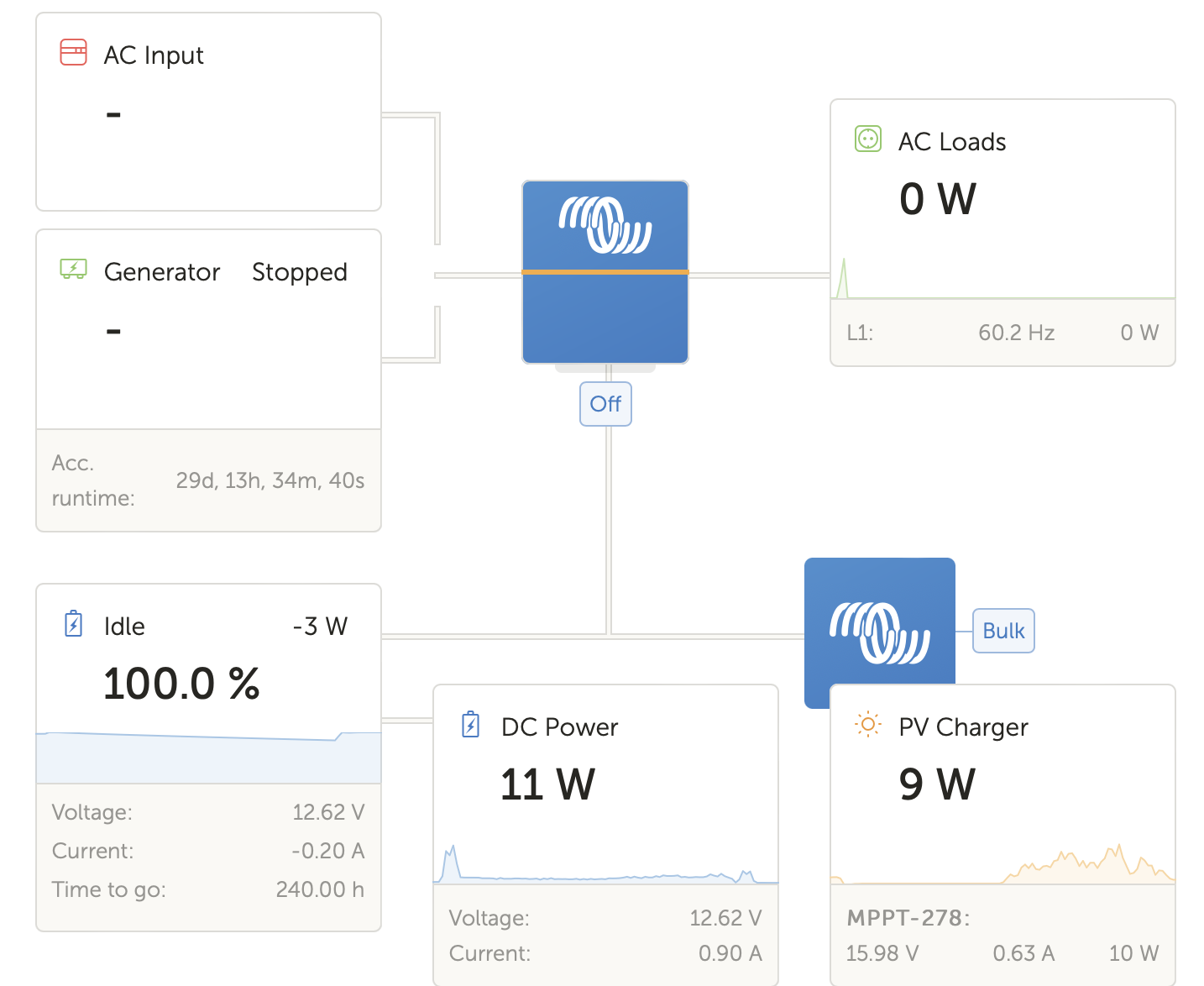
I have a new MPPT charger and a Quattro. Here is the screen showing when I login remotely to the Cerbo:

1654289337518.png


I don't quite understand why the boat is drawing 41W of power (DC Power), but it seems like 25W is coming from the MPPT and 16W is coming from the battery. Shouldn't the battery be charging? It's only showing 89% and declining? It's a bright, sunny day, and the solar cells can put out almost 150W. Why would it not charge the battery and fulfill the full 41W of demand?

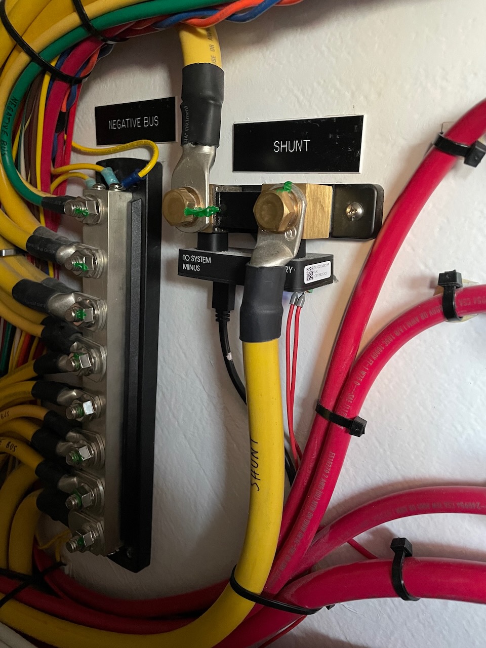
Is my system not wired correctly?


Thanks for any help?


MPPT ControllersMultiPlus Quattro Inverter Chargercerbo gxSolar Panel
1654289337518.png (95.3 KiB)
1 comment
2 |3000

Up to 8 attachments (including images) can be used with a maximum of 190.8 MiB each and 286.6 MiB total.

cory-eaves avatar image cory-eaves commented ·

Ok, I got out to the boat today, and as I suspected, the solar charger was wired directly to the battery. I changed it to be wired to the negative bus (after the shunt), and now the display makes more sense:


screen-shot-2022-06-11-at-61015-pm.png


At this moment, 9W coming from the solar, 3W leaving the battery, both supplying a load of 11W. The SOC is working correctly now too.

Thanks, everyone, for the help.

0 Likes 0 ·
4 Answers
Matthias Lange - DE avatar image
Matthias Lange - DE answered ·

You have a load of 41W.

16W are coming from the battery and 25W are coming from the MPPT.

16+25=41

11 comments
2 |3000

Up to 8 attachments (including images) can be used with a maximum of 190.8 MiB each and 286.6 MiB total.

cory-eaves avatar image cory-eaves commented ·
Why am I not getting 41W coming from the MPPT? Or 100W coming from the MPPT and 41W going to the load and 59w going to charge the battery?
0 Likes 0 ·
snoobler avatar image snoobler cory-eaves commented ·

DC system is a catch-all. It's where every leftover source/drain goes. Your Quattro has an idle power. My 48/5000 burns about 27W just by being on with no AC loads, so that's part of your DC loads.


Your PV only puts out 150W in perfect conditions at one moment in the day. At all other times it puts out less. It is actually very rare for a solar panel to deliver maximum rated output due to several factors.


Panel shading/partial-shading can dramatically reduce panel output.


What battery chemistry and what float voltage?


Is your shunt properly configured for solar charging?

0 Likes 0 ·
cory-eaves avatar image cory-eaves commented ·
Why am I not getting 41w from the MPPT and going to the load? Or getting 100w from the MPPT with 41w going to the load and 59w charging the battery?


How do I get the MPPT to charge the battery? Wait for the voltage to fall?

0 Likes 0 ·
snoobler avatar image snoobler cory-eaves commented ·

Again,

What battery chemistry?

What is your float voltage setting?

0 Likes 0 ·
cory-eaves avatar image cory-eaves snoobler commented ·
Sorry, I am sure I am not asking this clearly. My batteries are regular AGM. I am accessing the MPPT through the Cerbo remotely, and I don’t see an obvious way to set the float voltage, but assume it’s set to the default.


I have a SmartShunt which is monitoring the battery. I have about 16W of load that is on my 24hr circuit, and I am wondering if it’s somehow not wired correctly. What I have noticed is that the about 16W of load seems to permanently come from the battery and the MPPT seems to ramp up and down to fill the rest. I understand all about shading and output, but I am wondering if the MPPT is somehow not “seeing” the baseline load.

Right now, based on sun, the MPPT could be putting out a lot more, but maybe I’m missing something. I’d like to see the battery at 100%, the load on the battery at zero, and all the load supplied by the solar.

Again, appreciate all the help. Maybe I am missing something.

0 Likes 0 ·
snoobler avatar image snoobler cory-eaves commented ·
AGM is the chemistry.


Is your shunt flipped around?

0 Likes 0 ·
cory-eaves avatar image cory-eaves snoobler commented ·
Wouldn’t that reverse the reading for the whole load? I think the polarity is correct based on Seeing the charge go down during usage.
0 Likes 0 ·
snoobler avatar image snoobler cory-eaves commented ·
You should confirm the polarity is correct by confirming it is installed correctly. "I think" doesn't cut it.


If your SoC is dropping, but your voltage is not, something doesn't add up.

0 Likes 0 ·
cory-eaves avatar image cory-eaves snoobler commented ·
Yep. Fair enough. I’ll check it next time I can get on the boat.


Thanks

0 Likes 0 ·
snoobler avatar image snoobler cory-eaves commented ·
The more I think about it, the more I expect it's backwards.


If your battery is maintaining the float, but the SoC is going down, then it's backwards. Flipping the shunt around would read, 23W PV, 16W charging and 9W DC loads.

0 Likes 0 ·
cory-eaves avatar image cory-eaves snoobler commented ·

Ok, I was able to check and it looks like my shunt is installed correctly.img-0906.jpeg

0 Likes 0 ·
img-0906.jpeg (281.8 KiB)
elvis avatar image
elvis answered ·

IMO, it looks like your battery is fully (or mostly) charged. The MPPT appears to be in float mode. What is your float voltage set to? Did you calibrate & sync the Shunt?

The panel and MPPT wont provide any more than needed. If you have plenty of sun and its not charging its likely because you're fully charged and in float mode. Put a bigger load on the system and the panel watts will increase to meet the demand.

2 |3000

Up to 8 attachments (including images) can be used with a maximum of 190.8 MiB each and 286.6 MiB total.

Sarah avatar image
Sarah answered ·

Your theory is sound - more sun means more output from the mppt and a battery that is charging. It does appear that something has been wired incorrectly. Have a look at nighttime when there is no output from the mppt. If the battery is says ‘charging’ when it should be ‘discharging’ you likely have a problem with the shunt being reversed. It is also possible that the mppt is going straight to the battery and bypassing the shunt. As far as DC system is concerned this number can be confusing as it is not a real measurement (unless you have a seperate shunt specifically set up as an energy meter). The Cerbo just tells you what it thinks the DC system is doing (mppt output + battery output). If you have a cabling issue this number will be wrong. Trouble shooting will involve tracking wires and looking at each component in isolation (with the others turned off) to see if the behaviour is what you expect.

2 |3000

Up to 8 attachments (including images) can be used with a maximum of 190.8 MiB each and 286.6 MiB total.

kevgermany avatar image
kevgermany answered ·

This is getting messy.

Three potential problems I can think of.

1 - shading on the panels. Easy to check/eliminate.

2 - wiring. I'm not convinced, the values look correct, but worth checking.

3 - charger settings. Seems most likely, battery voltage is too low to be charging. If the charger was charging it would be in the 14V region. Assuming it's a bluetooth model, download and connect to it via the Victron connect app. Use the cog wheel to go Into settings. Post screen shots of the charger/battery settings.

4 comments
2 |3000

Up to 8 attachments (including images) can be used with a maximum of 190.8 MiB each and 286.6 MiB total.

Hi,

To add to point 3: After signing into VRM in the VictronConnect app, you can also connect to the Cerbo remotely via the VRM tab and then connect to the MPPT and view all the settings. This would allow to making screenshots of the settings without being on site.

Kind regards,

Thiemo van Engelen

0 Likes 0 ·
cory-eaves avatar image cory-eaves Thiemo van Engelen (Victron Energy staff) ♦ commented ·

Thank you all for the ideas. A few things:


In terms of getting to the settings, I can see this screen when I am local and connect via Bluetooth and the app:85cae898-16ac-4c37-8b30-d5884476e882.jpeg


When I connect remotely via the Cerbo, I see the device screens here:

a7f65f84-293a-46f1-a002-d814f58b9a49.jpeg

a2dd5f90-1304-4e03-823e-6bb3a0342c6e.jpeg

But I do not see the place to set the detailed voltages, etc. Am I missing how to access this remotely?

My current theory is that they wired the MPPT negative directly to the batteries instead of to the other side of the shunt. My steady state load is about 16-20W, and even when the MPPT is putting out this much, the SOC is not getting “credit” for it. I think the SmartShunt is not seeing the current flowing into the battery from the MPPT. The SOC keeps declining, because the shunt thinks there is a drain, but even when the SOC is low, the voltage stays 13V.

This is a new build and the whole system was installed by a builder. They didn’t provide schematics and it’s very hard to trace all the wiring since it’s buried in the hull.

Thanks again for all the ideas and assistance.

0 Likes 0 ·
klim8skeptic avatar image klim8skeptic ♦ cory-eaves commented ·

Am I missing how to access this remotely?

Connect & Configure Remotely in the VictronConnect

There is a video for almost everything :) .

1 Like 1 ·
cory-eaves avatar image cory-eaves klim8skeptic ♦ commented ·

Got it, thanks! I was trying to do it through the web interface, and it looks like it requires the app.

0 Likes 0 ·