question

funkybigdude avatar image
funkybigdude asked

Pylontech US2000c Alarm - Internal Failure Alarm - Temperature Sensor Broken?

I have a system with 4 Pylotech US2000C + 4 Pylontech US2000 Pus 95.

My system consists of the following components and is grid connected

  • 3 x Victron Multipluss 48/5000/70
  • 1 x CerboGX
  • 2 x Mppt 250/100
  • 4 Pylotech US2000C
  • 4 Pylontech US2000 Pus 95.

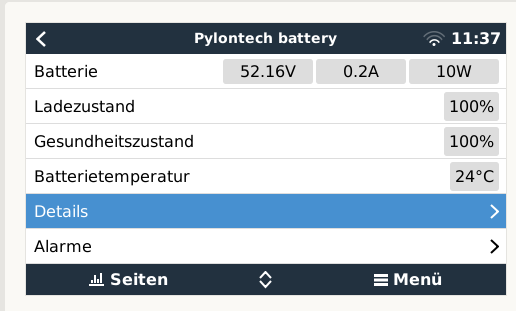
The system and the batteries have been working without problems since 04.May.2022.
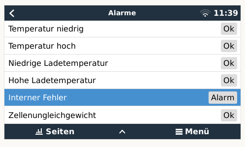
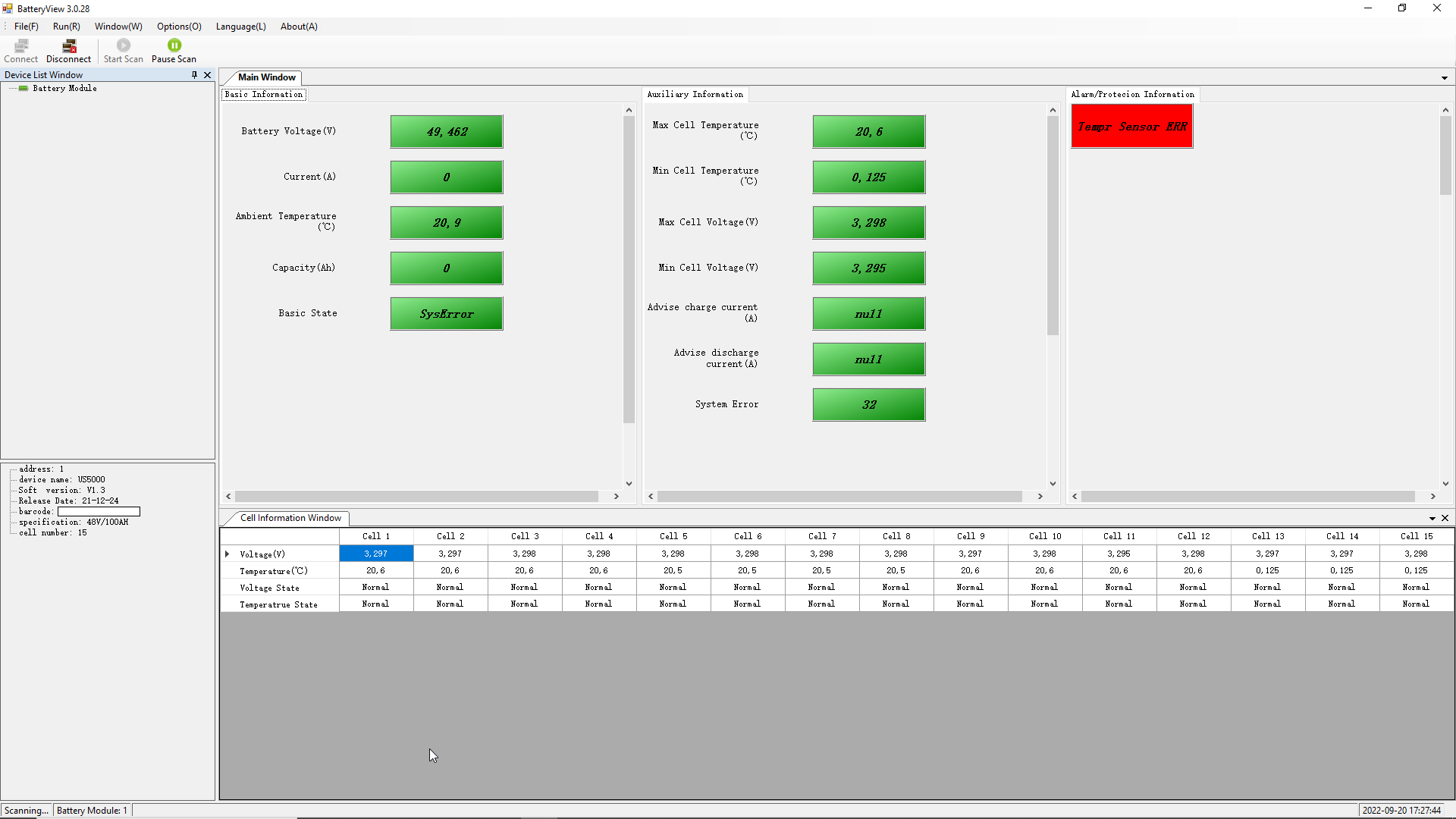
Since 26.May.22 the red LED on one of the US2000C is up and I get an alarm in the CERBO GX: "Internal Failure Alarm - 512"

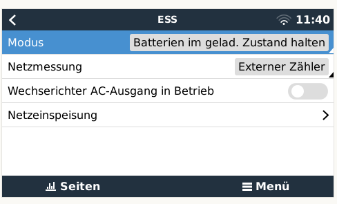
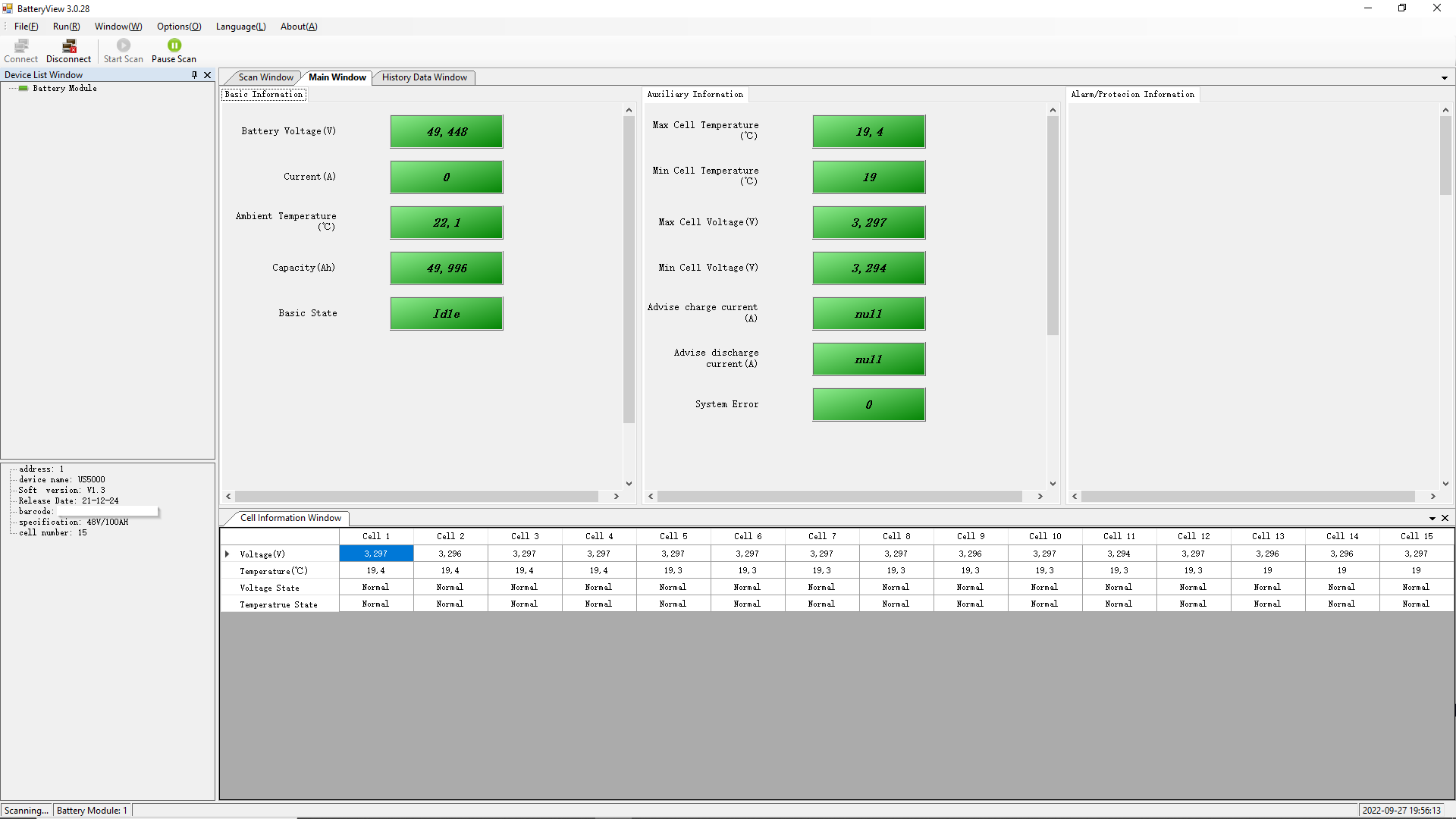
I have already run the ESS on "Keep Baterie Charged" for 3 days without success.

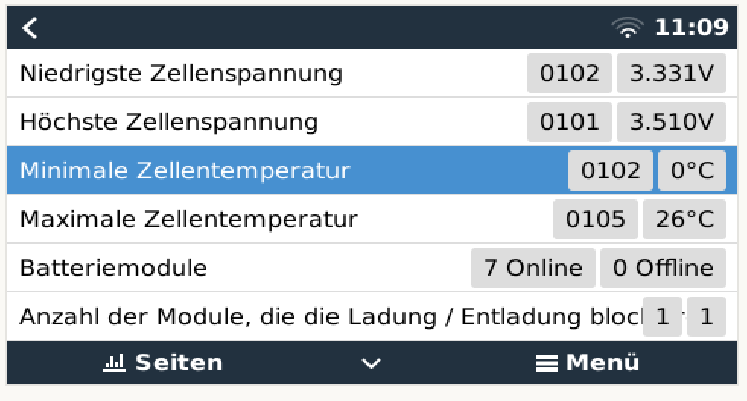
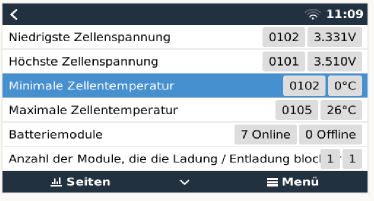
The batteries are in a rack in my house and have the same ambient temperature in the rack. However, one cell shows me 0 degrees Celsius as the minimal temperature.

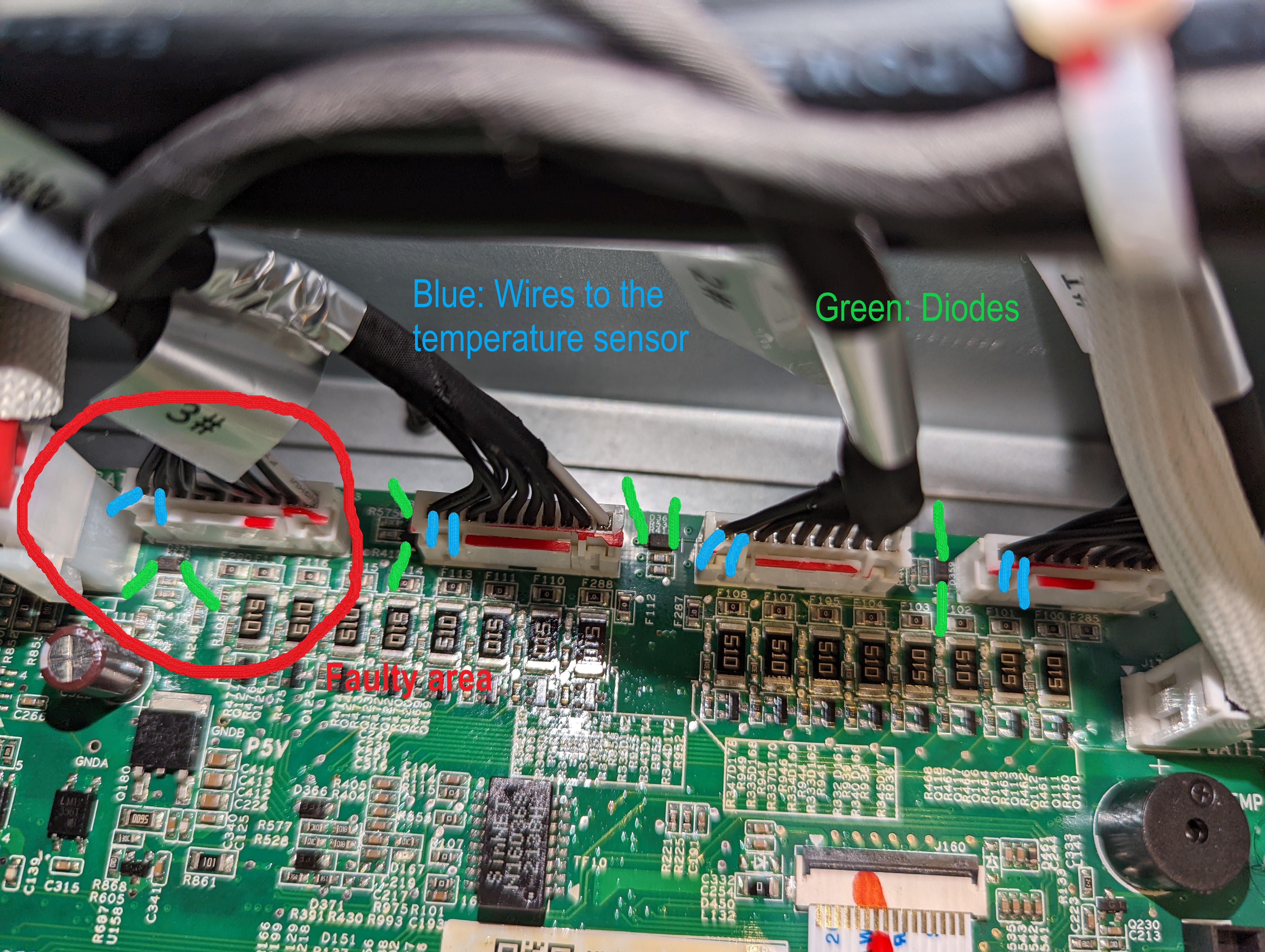
Is this a fault that I can correct or does this battery need to be changed?

1653903804400.png

1653903590668.png

1653903469849.png

1653903661207.png

@Ned Yu (Pylontech)

Pylontechvictron
1653903342012.png (36.9 KiB)
1653903469849.png (24.4 KiB)
1653903590668.png (23.9 KiB)
1653903661207.png (21.3 KiB)
1653903804400.png (43.4 KiB)
2 |3000

Up to 8 attachments (including images) can be used with a maximum of 190.8 MiB each and 286.6 MiB total.

4 Answers
Guy Stewart (Victron Community Manager) avatar image
Guy Stewart (Victron Community Manager) answered ·

Hi @FunkyBigDude,

As mentioned by the alarm, that is an internal fault to the Pylontech battery and will need to be serviced by your Pylontech dealer. Contact them for more details about what needs to be done next to isolate the module and next steps.

There is nothing that can be done to help on the Victron equipment side for that specific error.

2 |3000

Up to 8 attachments (including images) can be used with a maximum of 190.8 MiB each and 286.6 MiB total.

holger Bleckwehl avatar image
holger Bleckwehl answered ·

This is a fault off pylontech battery.... maybe old firmware...

or a mistake of bms-system.. a had the same mistake on 2 pylontechs US2000C and US30000C

2 |3000

Up to 8 attachments (including images) can be used with a maximum of 190.8 MiB each and 286.6 MiB total.

rittschie avatar image
rittschie answered ·

I have exactly the same problem with a US5000! Anybody found a solution?

2 |3000

Up to 8 attachments (including images) can be used with a maximum of 190.8 MiB each and 286.6 MiB total.

rittschie avatar image
rittschie answered ·

I start my investigation to find the failure of my US5000

With the programm Batteryview and a USB RS232 Adapter with a handmade adaptercable, I was able to make a readout of the battery.

scan-ohne-sn.png

The readout shows me a temp sensor error. Cell 13-15 have only 0,125°C.

I startet to disassembling the battery to find the fault. Maybe, a cabel was not connected.
All cables are connected!

4 (10 pin) plugs from the Cellpacks are going to the main PCB.I measured that the 2 left pin´s from the plug, are for the temperature sensor and the other 8 pin´s for the single cell voltage, and maybe balancing.

faulty-area.jpg

I measured following voltage on the 2 left pin´s from pluged plugs on Pack 4 to 1 in "ON" and "fault" status of the battery. 4= 0,075V 3= 1,63V 2= 1,64V 1=1,63V

Oh, the fault is in the area of pack 4. Then I tried to find out whether the fault was with the temperature sensor in the cell pack or on the PCB. To do this, I disconnected the 4 connectors from the board and measured the resistances at the 2 pins towards the cell pack´s. Roundabout 12,3kohm on all 4 cell pack´s.

Ah, the temperature sensors are all ok.The fault is on the circuit board!

I then did the following examinations there:

Measure the voltage without plugging in the cell connector on the circuit board. (It only works for a very short time because the safety circuit immediately switches off the board).

The measured voltage at the corresponding pins has the following values: 4= 75mV 3-1= 3V

Then I measured the diode near the 2 pins of the connector on the board. The diode from the defective area for cell pack 4 has a resistance of 234 ohm. The other diodes (pack 1-3) have a resistance of 13.45 kohm.


It looks like the one diode is defective. Now I just have to find out which type of diode and replace it.

Hopefully the battery will then work.


faulty-area.jpg (2.8 MiB)
scan-ohne-sn.png (81.2 KiB)
1 comment
2 |3000

Up to 8 attachments (including images) can be used with a maximum of 190.8 MiB each and 286.6 MiB total.

rittschie avatar image rittschie commented ·

Some days later:

I removed the circuit board from the housing at the weekend. Yesterday, I desoldered the defective diode and soldered in a new zener diode 5.6V.

Today I mounted the PCB back into the chase and made a first test.

The battery starts up without turning on the red LED. The battery view shows no failure anymore 1664304895449.png

Now I have to test the battery on my Multiplus II!

nach-rep-ohne-sn.png

1 Like 1 ·

Related Resources

Victron Pylontech battery compatibility guide

Additional resources still need to be added for this topic