question

Jason - UK avatar image
Jason - UK asked

What's the lowest inverter operational DC input voltage of a 48V GX controlled ESS?

After several issues with a firmware update stopping my ESS working with a connected 40A sensor, I am finally getting the system work work as intended but one sticking issue is the voltage will not go below 41.2V, regardless to any settings I adjust. 1652348890653.png

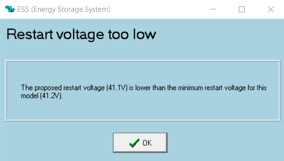
41.2V happens to be the minimum inverter restart voltage set out by the ESS assistant and is the only thing I can think is the issue, but why does the inverter cut out at the voltage the inverter should be restarting at, if my assumption is correct. If the DC input low shut down is 37.2V, why does it show down at 41.2v?

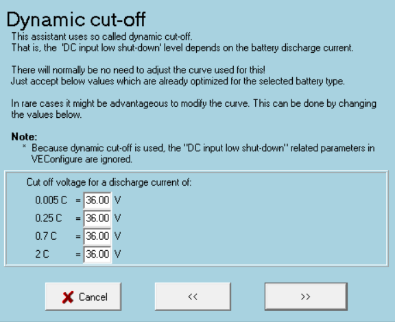
To test my assumption, I have set every voltage I can adjust to its lowest setting so see if there is any change, and still no change. Dynamic cut-off all set to 36V & sustain set to 36V in the ESS1652349243378.png 
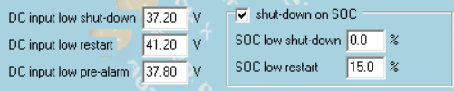
assistant. DC input shut-down set to 37.2V, DC input low restart set to 41.2V (the same voltage the inverter cuts out at???) My ideal minimum is 38V to maximise the useful energy within the battery whilst maintaining battery longevity.

I have even turned off Battery monitor in the remote console, as well as setting th minimum SOC to 0%, Ive turned off BatteryLife (set it to Optimized (without batterylife), DVCC off, Low battery voltage alarm disabled, still it will not go below 41.2V


Multiplus-IIESSVictronConnectAssistants48v battery
1652348890653.png (21.0 KiB)
1652349243378.png (22.9 KiB)
2 |3000

Up to 8 attachments (including images) can be used with a maximum of 190.8 MiB each and 286.6 MiB total.

2 Answers
Alexandra avatar image
Alexandra answered ·
@Jason

Ess has dynamic cut off voltages programmed for c rating loads. These will override the ones on the tab you are looking at.

What battery are you working like that?

10 comments
2 |3000

Up to 8 attachments (including images) can be used with a maximum of 190.8 MiB each and 286.6 MiB total.

Jason - UK avatar image Jason - UK commented ·

@Alexandra Im running Tesla modules. Even with the C rating set as low as it can go, it still cuts out at 41.2V. Its not the end of the world as the batteries have enough amps to cover me for a 24h period at the moment but I am testing the setup I have to know what can be done for future projects. The consultancy I work for are just starting to experience ESS demand on projects and as I wanted a ESS system for myself, I wanted something I can test different setups with but the Pylontech's I ordered never turned up after 3 months of waiting. Ended up with tesla batteries for the time being. 1652365305954.png

0 Likes 0 ·
1652365305954.png (62.9 KiB)
Jason - UK avatar image Jason - UK commented ·
@Alexandra so would I be correct in saying I need to delete the ESS assistant to allow the inverter to continue below a battery voltage of 41.2v? Thanks for you assistance.
0 Likes 0 ·
Alexandra avatar image Alexandra ♦ Jason - UK commented ·
@Jason

If it is that important to you. But you can't control depth of discharge unless you use AC ignore or Virtual switch.

Is the Telsa communicating with the system at all? Does the telsa voltage collapse at all when reaching the lower voltage when a load comes on? You may need more than the minute by minute monitoring to work it out.

The system could have lower voltage, the shutdown is triggered, then with no load the tesla voltage jumps back up.

0 Likes 0 ·
Jason - UK avatar image Jason - UK Alexandra ♦ commented ·

@Alexandra continuing from by below reply, I did some load tests on the inverter and it performed exactly as expected down to 41.2v. I managed to get the inverter to run for a short while just over 6kW to give the batteries a bit of a work for a short period before it started to throttle back. The inrush when I applied the 6kW load appeared to give a 2v drop across the DC cables for a few milliseconds then levelled back off to less than 0.5v drop. One observation is the temperature increase across the cable when under load is inconsistent. The closer it get to the inverter the greater the temperature. 20*C difference from battery end to inverter with a starting temperature of 16*C, and rising along the cable with 36*C on the final connection to the inverter.

The tesla batteries have my own BMS which only provide a break in a single wire to stop the inverter on under / over voltage set at 36v / 50.5v, and another fail safe for over voltage set to 51v which breaks the remote on / off link. My 'absorption' is set to 49.9, float 49.8v

0 Likes 0 ·
Jason - UK avatar image Jason - UK commented ·
@Alexandra I further explored this issue over night and noticed that the inverter stopped inverting at the moments of sudden high loads pulling the voltage down to the 41.2v but within the capacity of the inverter. It does appear to be dynamic cut-off but still not close enough to the 36v I have set it at. As soon as that high load has done. the inverter starts inverting again for a smaller load.
0 Likes 0 ·
Alexandra avatar image Alexandra ♦ Jason - UK commented ·
@Jason

I am thinking the battery bank voltage is collapsing under load

Maybe you have cell imbalances?

0 Likes 0 ·
Jason - UK avatar image Jason - UK Alexandra ♦ commented ·
Morning @Alexandra. I spend yesterday running a few tests. Cells are >0.1v difference, at 23v per battery module so I ruled out any cell imbalances initially. Then with really crappy weather yesterday, there was little solar energy so no full charge up to 24.9 per module, 49.8v total. Assuming the inverter would cut off at 41.2V as it previously did, yesterday the inverter kept operating at a reduced output down to 40.8v exactly or exactly 60% SOC. Is there an algorithm that reduces the low voltage limit over time and the associated discharge rate? I had made no changes to the system over the weekend but its behaviour was different to my benefit and I can not work out why now it operated down to that SoC or the voltage of 40.8v as that does not relate to any setting i currently have. I assume 36V is the absolute minimum voltage the inverter can operate at.
0 Likes 0 ·
Jason - UK avatar image Jason - UK Jason - UK commented ·

Each group of cells was between 3.81v and 3.83v at the time of measuring the groups of cells. 6 in series per modules, both modules the same.

0 Likes 0 ·
Alexandra avatar image Alexandra ♦ Jason - UK commented ·
@Jason - UK

Have you tried not using the shutdown on SOC option. You are ysing it in combination with the voltage option, the VE Bus SOC is probably out.

0 Likes 0 ·
Jason - UK avatar image Jason - UK Alexandra ♦ commented ·

Good idea. I didnt think of that one. I have turned off Shut down on low SOC, I'll let you know how that goes but it might be a while, good weather predicted for the foreseeable. :-)

0 Likes 0 ·
hardy-tuner avatar image
hardy-tuner answered ·

Normaly with ESS you Can’t go under 41,2V, except grid fails, then the voltage goes down to 38V ( or maybe 36V if needed, but not recommended for battery lifetime)

1 comment
2 |3000

Up to 8 attachments (including images) can be used with a maximum of 190.8 MiB each and 286.6 MiB total.

Jason - UK avatar image Jason - UK commented ·
@hardy tuner Yes, you are spot on. When I first got my Multiplus, I assumed the voltage would go lower like another inverter I had seen. I can get it down to 36v at a push like like you mention, its best not to to help maintain battery lifetime. Happy with my set up now but when I first set it up, it took me a while to set up the Multiplus II.
0 Likes 0 ·