question

athlonfx avatar image
athlonfx asked

Pylontech Internal Failure after adding a third module

Hello everybody,

after adding a third Pylontech US2000, I'm experiencing the Pylontech battery alarm Internal Failure.

First of all, my previous setup:

Multiplus-II GX (Venus OS 2.82), combined with 2 Pylontech US2000B-Plus (according the the part number) and an EM24, configured as a grid tied ESS system (AC IN connected only); grid tied PV micro inverter (Hoymiles)

The setup ran just fine, no problems at all. Even high load (2000W, deliberately limited in the settings) never threw any alarm.


Then I decided to add another US2000, this time it's a US2000C.

The SOC indicator of all modules showed the same number of leds lighting.

I connected the cables as mentioned in the manual and the Multiplus-II GX detected them correctly, the US2000C being the master.

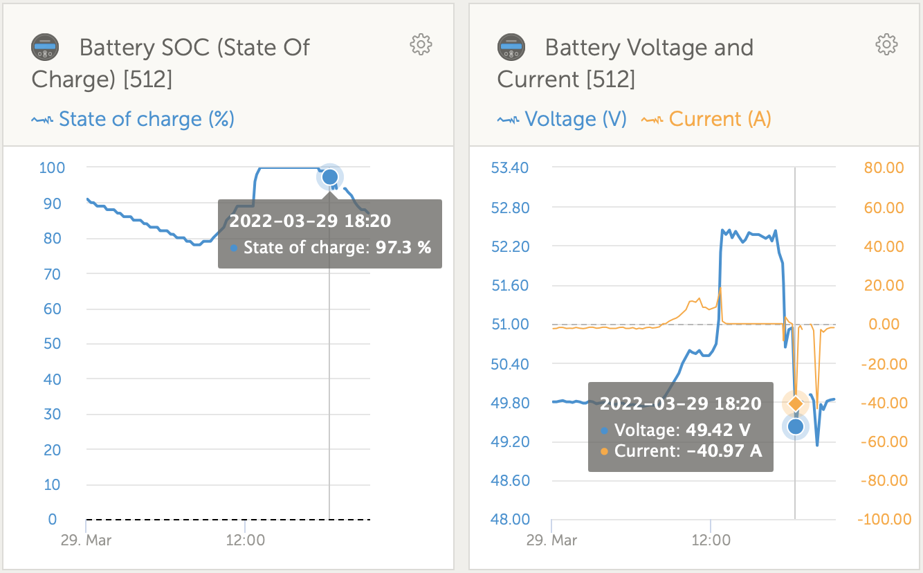
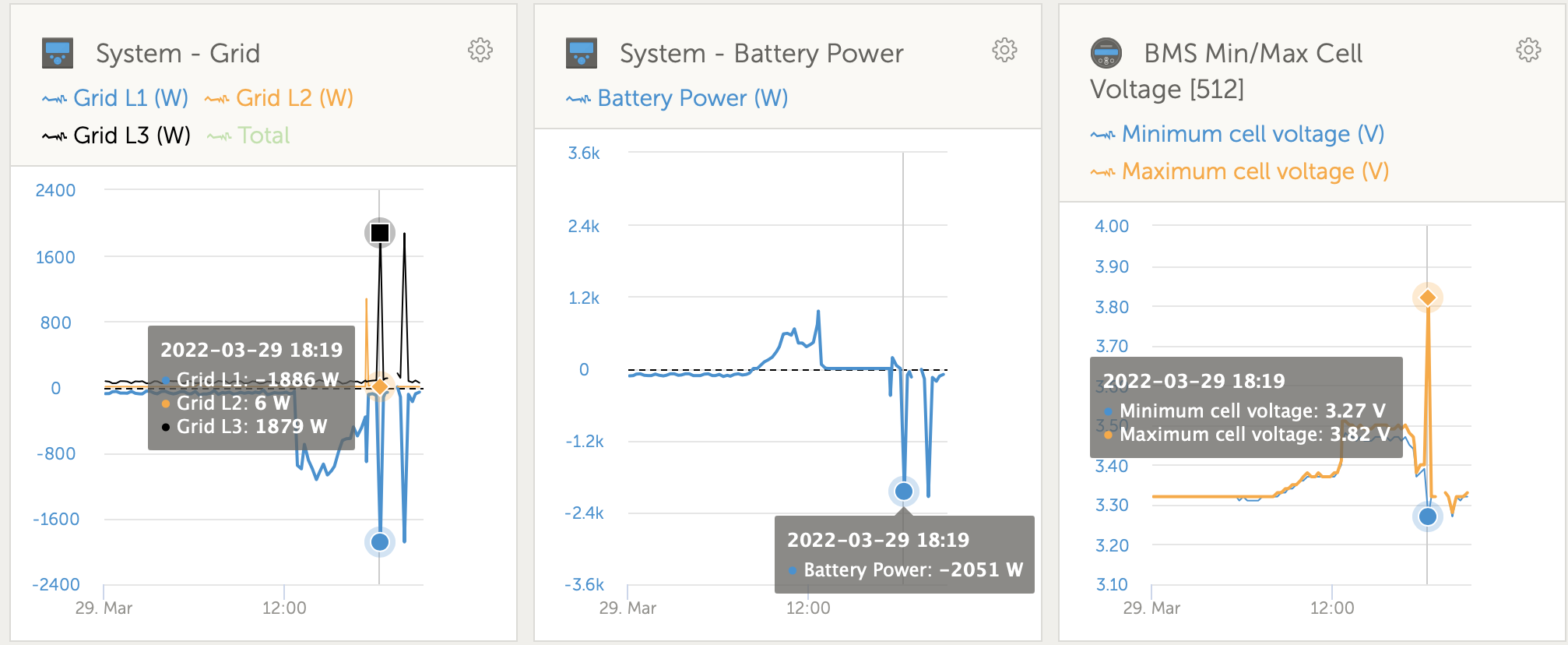
I started to use a fan heater (1400W) the same evening, eventually the new module threw an Internal Failure alarm. Strangely, just 2-3 minutes earlier, the Maximum Cell Voltage shot from 3.29 V to 4.10 V. Just before that event, the Minimum Cell Voltage and Maximum Cell Voltage were just 0.02-0.03 V apart. Switching it off and on got it back working again.

The next days, the error came back again, even at night where there was almost no load (100-150W) at an SOC of 49%.

I kept the modules in Keep batteries charged mode over night. The next morning the Multiplus-II GX still reported being in Absorption mode.

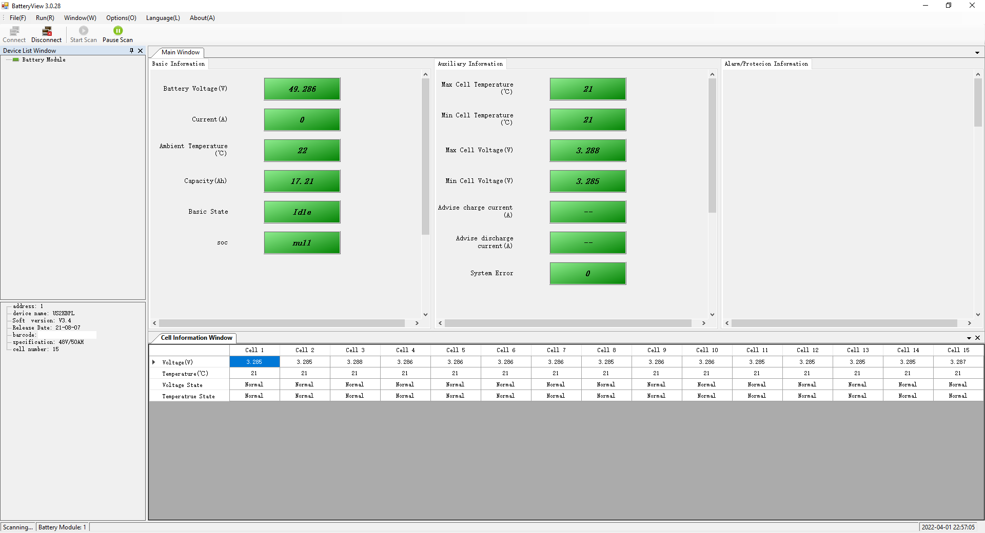
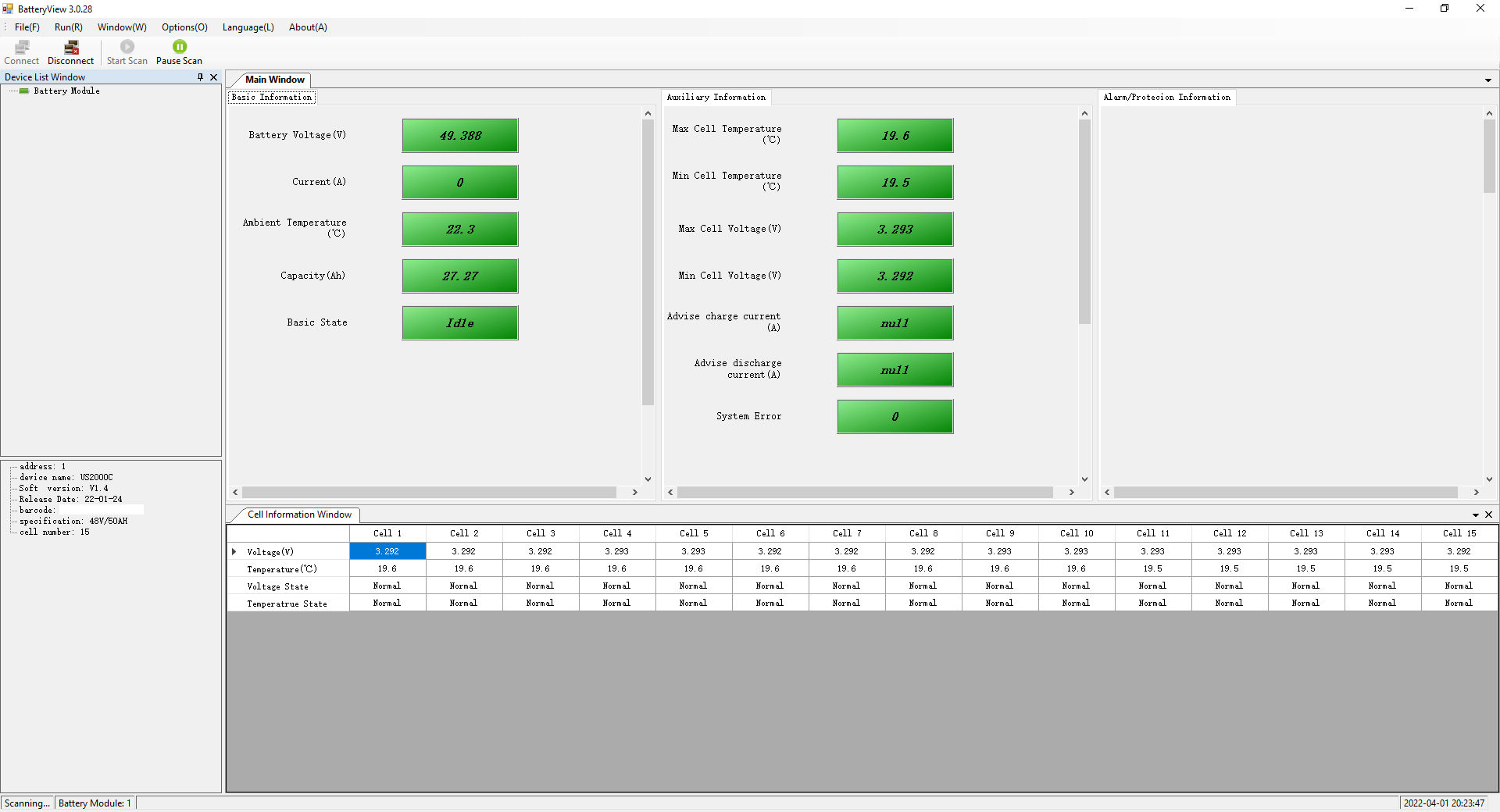
Unfortunately, the error occurred again. So yesterday evening, I started to charge module per module separately (Keep batteries charged mode, all wires to the other modules disconnected). The SOC of all modules was off, especially from the new one. Every module was in Absorption mode when I ended the charge, the difference between the Minimum Cell Voltage and Maximum Cell Voltage was just 0.02 V. Every module didn't light up the SOC leds, so according to the manual, the module was in idle.

So I tried it another time. This time, I had some load (800-900 W, 25 minutes), the error didn't occur. Some time later (1 hour) I had some more load on it again (2100W, 42.6A, 49.56V, Minimum Cell Voltage 3.28V, 4.10V) and the error came back.

Was I not patient enough and should've kept it in Keep batteries charged mode until Absorption ended? Can Absorption end at all?

Does anybody have a clue the problem is and how it could be solved?

Thanks in advance.

Multiplus-IIPylontechalarm
2 |3000

Up to 8 attachments (including images) can be used with a maximum of 190.8 MiB each and 286.6 MiB total.

8 Answers
Guy Stewart (Victron Community Manager) avatar image
Guy Stewart (Victron Community Manager) answered ·

That error is usually less serious than it sounds. Typically resolved by bringing all the modules to a full charge individually and then keeping the whole system in absorption/balance voltage for as long as possible, 24 hours continuous would be ideal.

2 comments
2 |3000

Up to 8 attachments (including images) can be used with a maximum of 190.8 MiB each and 286.6 MiB total.

athlonfx avatar image athlonfx commented ·
Hi Guy, thank you for your answer.


Do you recommend that I charge them individually again?

Should I set the ESS mode to Keep batteries charged for 24 hours or use Scheduled charging for 24 hours?

The Absorption voltage is set to 52 V, as in the Manual by Victron. Can I keep it there or should I increase it? The modules didn't seem to do much at all.

0 Likes 0 ·
Guy Stewart (Victron Community Manager) avatar image Guy Stewart (Victron Community Manager) ♦♦ athlonfx commented ·

They should all be brought to 100% individually before joining them together to minimise the time required for the internal balancing.

The internal balancing is INCREDIBLY slow, it is not designed to balancing multiple battery modules, but just the normal variation between battery cells internal to the module, so using it to try and balance multiple modules might never get there.

Even once all individually charged to 100%, the balancing is still quite slow, but as long as all batteries are showing 100%, then they are in the sufficient voltage range to balance so do not require any additional tweaking to voltages (nor will it help).

The balancing circuit will only do what it can do to it's max current (and it's negligible from a system monitoring perspective, so you just need to watch the max/min cell voltages over a few cycles).

Keep batteries charged for 24 hours would be the setting I'd use. It should force a 100% charge from the grid.

0 Likes 0 ·
athlonfx avatar image
athlonfx answered ·

I didn't recharge every module individually, because all of them were at 100%, but left the 3 modules in "Keep batteries charged" mode for 24 hours. I increased the Absorption voltage to 52.5 V, the Float voltage to 52.0 V, the Absorption time to 2 hours (voltages are a recommendation in another forum).

After that, I charged them again individually for about 1 hour. Every module showed 100% from the beginning.

Then I connected the main wires between the modules (no cable connected to the Multiplus-II GX), turned them on and started them, let them rest for another hour. According to the SOC leds, they were in idle after a few minutes.

Then I reconnected them to the Multiplus-II GX, kept them in "Keep batteries charged" for 6 hours. All modules started idling after a few minutes.

After that I switched back to "Optimized without Battery Life".


Today, I put some load on it again (1 kWh in 3 hours, cooking, gaming), the error didn't occur.


When being charged, there's still the difference of 0.02-0.03 V between Minimum and Maximum cell voltage. My guess is that the BMS doesn't work more accurately. That's the same difference as I had before I added the third module.


I'll switch back to Absorption voltage 52.0 V, Absorption time 1 hour, Float voltage 51.0 V in a few days, if the error doesn't occur again.


If I have to do it again, I'll do it like this:

  1. charge every module individually up to 100%, let it sit there for some hours (at least until the SOC leds turn off and the RUN led blinks -> idle)
  2. connect the main wires and communication wires between the modules (no wires to any other device), switch all of them on, start them with the SW button, let them sit there again (at least until the SOC leds turn off and the RUN led blinks on all modules -> idle)
  3. connect the rest of the wires (main wires and CAN wire to the Victron device)
  4. switch on the Victron device and keep the modules charged for 24 hours ("Keep batteries charged" mode)

@Guy Stewart (Victron Community Manager) , what do you think about the above mentioned steps?

2 comments
2 |3000

Up to 8 attachments (including images) can be used with a maximum of 190.8 MiB each and 286.6 MiB total.

It sounds like you got it working, so that's good news.


I would not recommend charging or discharging a managed battery without the communications cable connected.


Thanks for the detailed reply btw, I am sure someone will find it a useful reference in the future.

0 Likes 0 ·
athlonfx avatar image athlonfx Guy Stewart (Victron Community Manager) ♦♦ commented ·

Thank you for your answer, @Guy Stewart (Victron Community Manager). I edited step no. 2 and added " and communication wires ".

This step was shown in a video, but without the communications wires. In the Pylontech manual it's recommended to let the modules balance for at least 15 minutes if there was a change in the array (all cables connected, idling).

0 Likes 0 ·
athlonfx avatar image
athlonfx answered ·

And just when you think the problem is solved, it occurs again.

At a load of 2051W on the battery, it showed Minimum Cell Voltage 3.27V, Maximum Cell Voltage 3.82V. Any ideas, @Guy Stewart (Victron Community Manager)?


Btw. the last couple of days we had a lot of sun, so the modules were full for quite a few hours per day (maybe a short discharge of a few minutes or so). The Multiplus-II GX never showed Float, as far as I saw. Is it normal that it stays in Absorption forever? Or are my modules still not balanced right?

Screen Shot 2022-03-29 at 9.20.46 PM.png

Screen Shot 2022-03-29 at 9.11.28 PM.png


2 |3000

Up to 8 attachments (including images) can be used with a maximum of 190.8 MiB each and 286.6 MiB total.

Dave Rae avatar image
Dave Rae answered ·

Have you got access to the Pylontech (BatteryView) software to access the module directly through the console port? That way you can pinpoint the issue to a more accurate degree. Could be a bad pouch cell, or a BMS problem..... Also even though you have the new C as the Master I wonder if there is a conflict with the older batts older firmware?? Just a thought.

2 |3000

Up to 8 attachments (including images) can be used with a maximum of 190.8 MiB each and 286.6 MiB total.

athlonfx avatar image
athlonfx answered ·

@Dave Rae thank you for your input. I ordered a USB to RS232 interface and an RS232 cable. I've got an old telephone cable and a patch cable for the side of the module. I found the pinouts for both US2000 revisions in another forum. I'll manufacture the cables as soon as I get the parts. Hopefully, it will work. I found the BatteryView Software (version 3.0.28) somewhere online, which should work according to information I found in another forum.

As soon as I get data from the modules, I'll post it here. And I'll share the pinout information, when I know it's correct.

Regarding Firmware issues: I read in another forum, that there is a bug in the firmware version 1.7 of the US2000C which lead to pretty similar effects. It was fixed by a firmware upgrade. Therefore I'm pretty curious about the firmware version of my module.

I really appreciate the information I receive here, thank you very much.

2 |3000

Up to 8 attachments (including images) can be used with a maximum of 190.8 MiB each and 286.6 MiB total.

athlonfx avatar image
athlonfx answered ·

I was able to manufacture cables for the US2000C and for the US2000B-Plus modules and could establish a connection to each module.

The US2000C had the firmware V1.2, both of the US2000B-Plus V3.4.

I was able to upgrade the firmware of the US2000C module to V1.4, the newest firmware I could find.

So I thought it would be a good idea to upgrade the firmware of the US2000B-Plus modules, too. Sadly, I erred on a post in another forum and installed the wrong firmware, I might have bricked one of the module.

I hope at least the issue with the US2000C module is solved, but I'm not very confident yet.

I think there is no significant cell drift, at least some good news.

US2000B_Plus_Front.PNGUS2000B_Plus_middle.PNGUS2000C_after_update.PNG


1 comment
2 |3000

Up to 8 attachments (including images) can be used with a maximum of 190.8 MiB each and 286.6 MiB total.

klim8skeptic avatar image klim8skeptic ♦ commented ·
You have been advised to fully charge each battery fully, before combining them.


That is good advice.

0 Likes 0 ·
athlonfx avatar image
athlonfx answered ·

Hello everybody,


I promised to share the information regarding the cables. There's a post in another forum (I hope it's ok to post it here) which contains a link to Google Drive. If you open the link, you'll find an archive with the BatteryView software, an archive with 2 firmware binaries and a pdf file. The pdf file contains the information needed to manufacture the corresponding cable. The RJ11 table shows the port side, the RJ45 table the cable side, which I found confusing.


The BatteryView software was the one I used to update the firmware of the US2000C module. As source I selected the firmware archive from the Google Drive link, which contains a V1.4 bin file and a V2.7 bin file. There seems to be different revisions of the US2000C module.


ATTENTION: The firmware in the archive seems to be only compatible with US2000C modules (maybe US3000C, too?!?). I bricked a US2000B-Plus with this firmware archive. The BatteryView software does NOT prevent flashing incompatible firmware.


V1.4 is installed on my US2000C since the 1st of April and so far it hasn't thrown the error again, despite some load (on only 2 modules) and discharging to an SOC of 30%. I'm slightly optimistic that the problem is solved with the new firmware.

2 comments
2 |3000

Up to 8 attachments (including images) can be used with a maximum of 190.8 MiB each and 286.6 MiB total.

jrgilchrist avatar image jrgilchrist commented ·
Hi I'm now having the exact same problem as you! Did you find a solution?
0 Likes 0 ·
athlonfx avatar image athlonfx jrgilchrist commented ·

@Jrgilchrist the problem hasn't occurred again since I upgraded the firmware to version 1.4. I got both BatteryView and the firmware archive from the above mentioned Google Drive link.

There is more than one revision of the US2000C and there are several versions of the US2000 family. The wrong firmware will brick your module!

My US2000C has the part number US2000CB4E200102.

Pylontech does NOT recommend upgrading firmware on your own, they want you to contact them beforehand so that they can send you a compatible firmware file.

If the part number of your module is the same, the firmware upgrade should work, I assume.

Regarding my bricked module (one of the non-US2000C), I contacted Jeff from Pylontech and provided the part number of this module, which was enough to determine which firmware is suitable.

0 Likes 0 ·
holger Bleckwehl avatar image
holger Bleckwehl answered ·

Be carefull with firmware-updates !! There are several versions for different types.

Maybe you could find the right here : https://www.effekta.com/downloads/

i had the same mistake in US2000C, there was BMS defect.

And the same on US3000C, there a update was successfull.

So it may be different

2 |3000

Up to 8 attachments (including images) can be used with a maximum of 190.8 MiB each and 286.6 MiB total.