question

anrich avatar image
anrich asked

MultiPlus II shuts down when grid fails

Note: please see my latest update for additional information and findings.

---

Hi all,

I've been having issues with my MP2 since installation. Every so often when the grid fails ("load shedding", substation trips, etc.) the MP2 shuts off for about a minute before starting up again).

System:

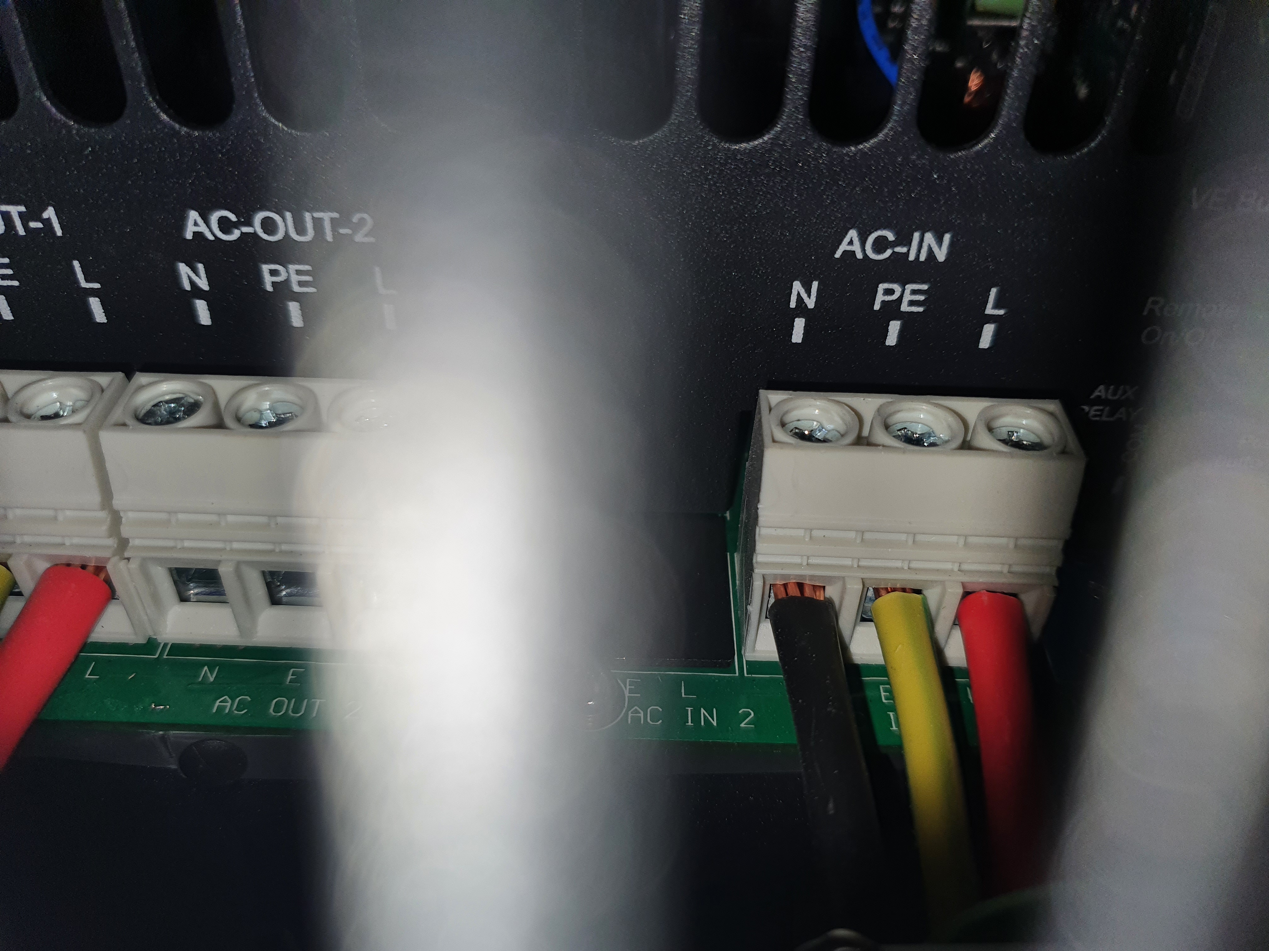
  • 1 x MultiPlus-II48/5000/70-50 230V
    • Firmware: v490
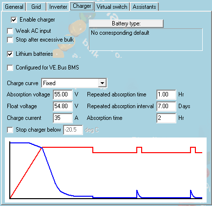
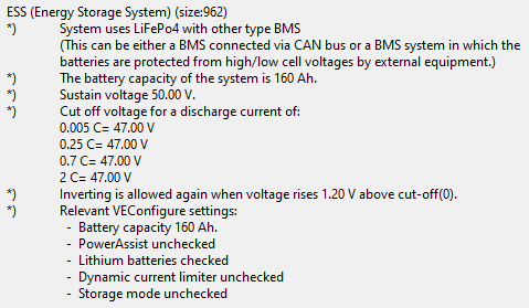
  • 1x BSL Battery LiFePO48 Battery 8.2kWh (160Ah)
  • 1 x SmartSolar MPPT 250/100-Tr VE.Can
  • 12 x LONGi 450W mono panels
  • Cerbo GX
  • ET112 Energy Meter

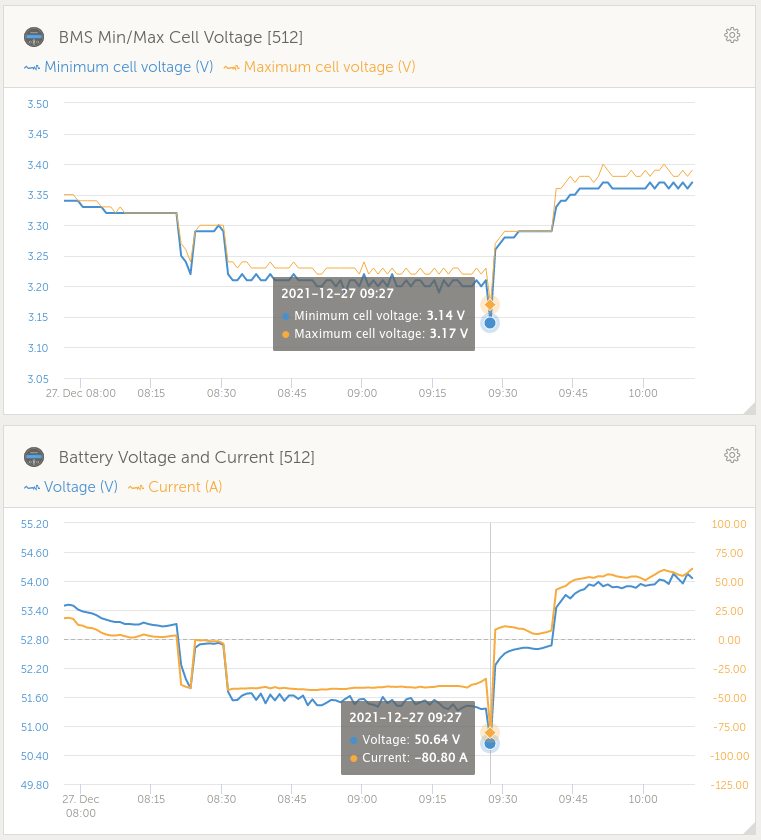
At first I suspected a battery (BMS or otherwise) issue, due to the fact that the shut off coincides with "Low battery voltage" warnings and alarms, as well as "High DC ripple" warnings. There's a whole thread about this. I however do not believe this is actually the issue, but rather just a symptom.

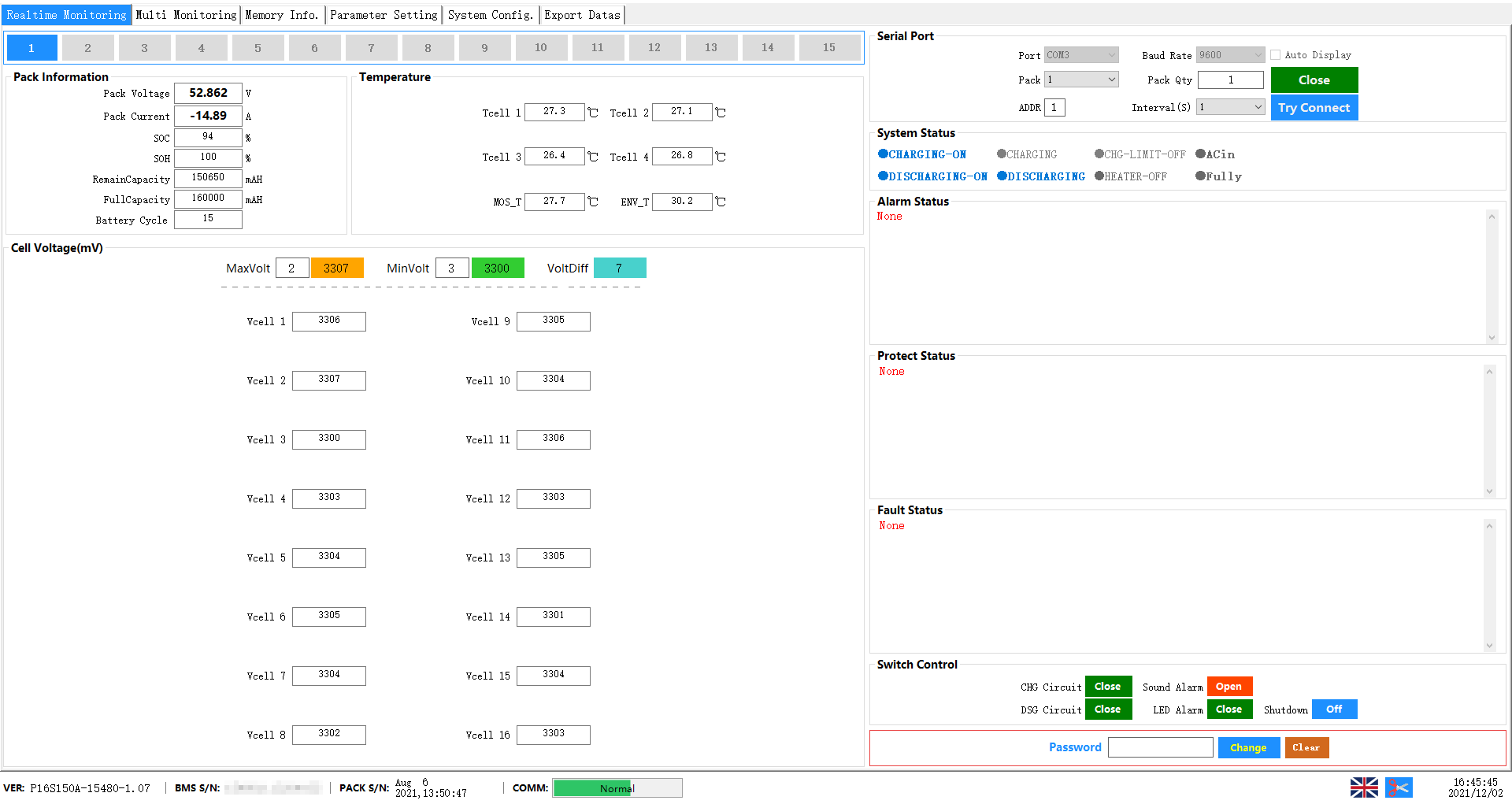
A battery supplier technician was on site a few weeks ago to inspect the battery, and reported that everything seems fine (checked battery params via RS-485). He said:

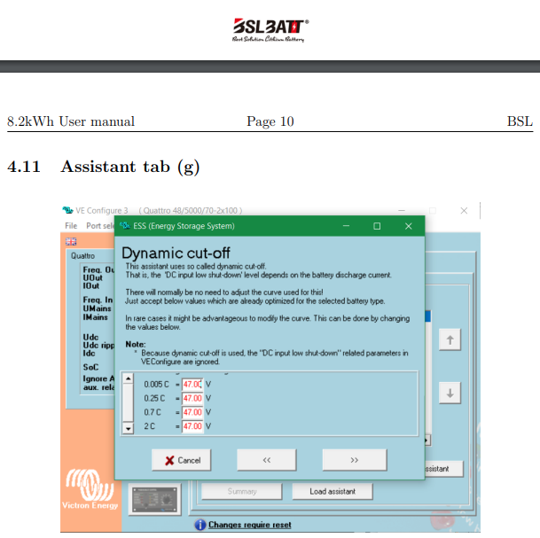
There's a known issue with the MP2 and BSL and FreedomWon batteries. The MP2 has some low voltage offset bug where it would shut down on a battery voltage that isn't actually too low. The issue has been reported to Victron.

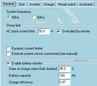
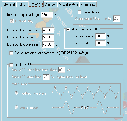
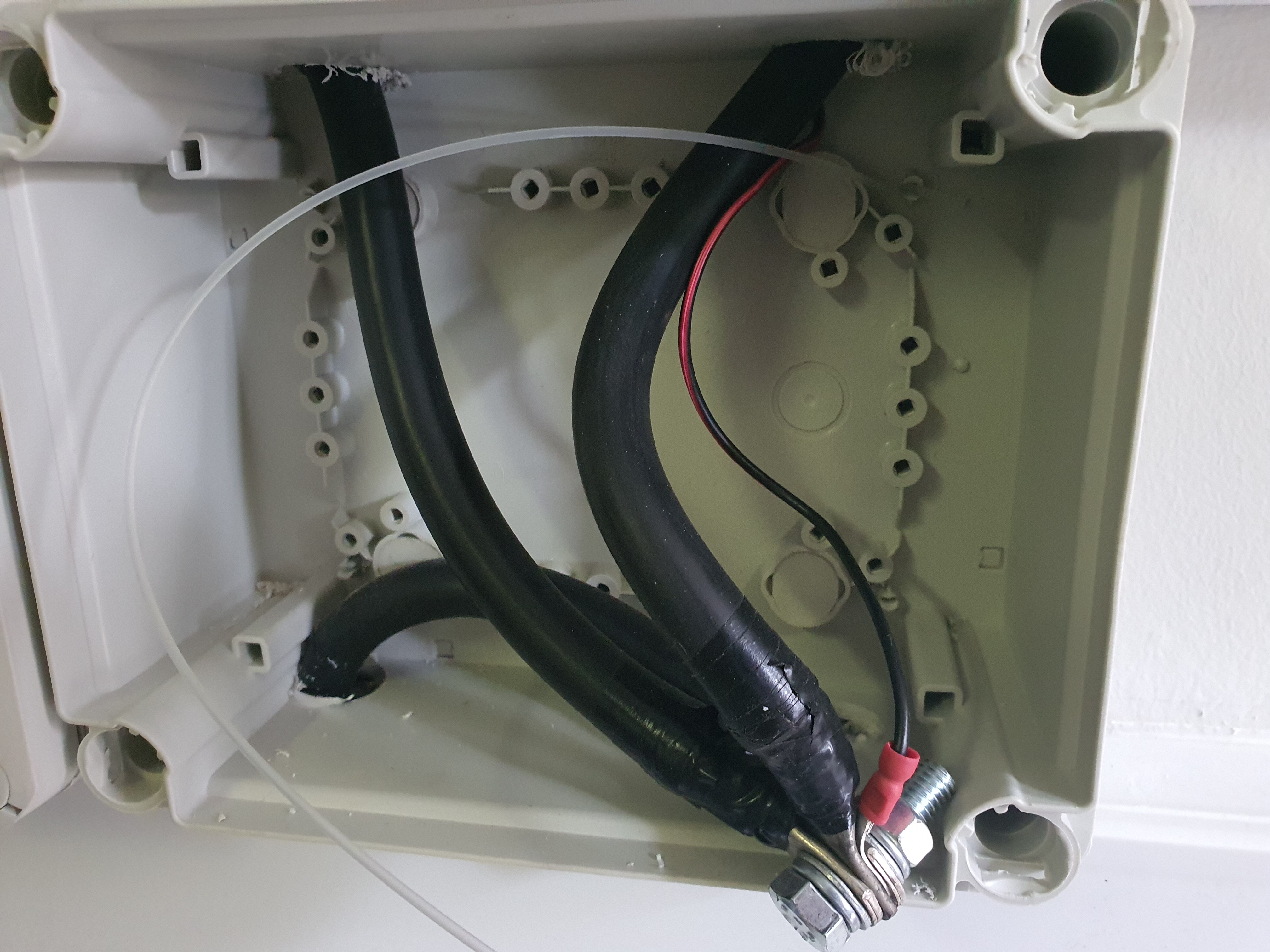
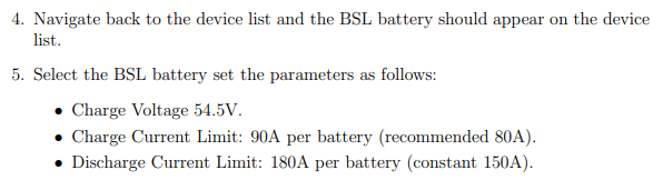
He suggested the installer set the "DC input low shut-down" lower as a workaround for now, until Victron fixes the bug. They set it to 46.80V (at this point the BMS should shut down the battery in any case). They also checked all wiring and replaced all fuses as a precaution.

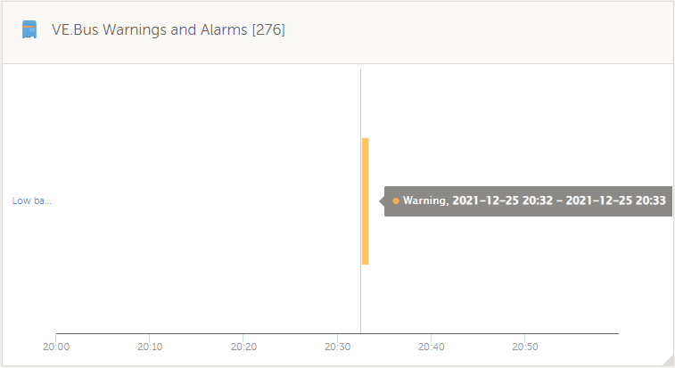
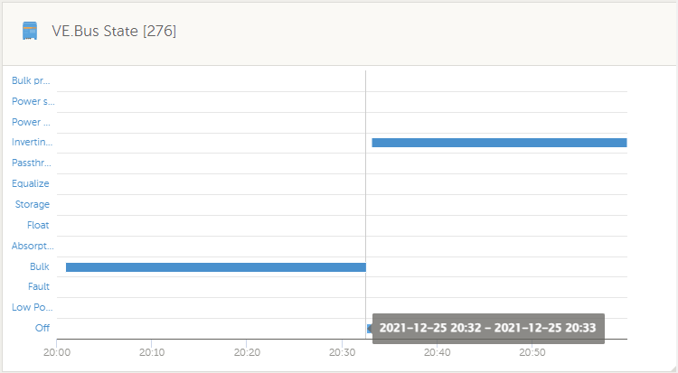
After this, the issue seemed to go away. There was a "Low battery voltage" warning at one point, but no alarm and the system didn't shut down. However, last night when the grid failed (minisub explosion led to panel trip at substation, i.e. probably brownout) the MP2 shut down again for a minute. What is very strange is that there was only a "Low battery voltage" warning - no alarm. I don't understand why it shut down on a warning.

I am skeptical that the cause of the issue is actually a MP2 bug, since this happened on v481 and v490 firmware. Does anyone know about this bug?

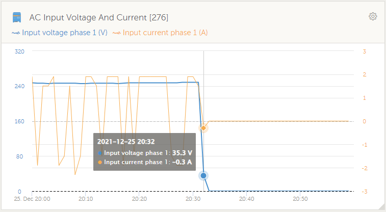
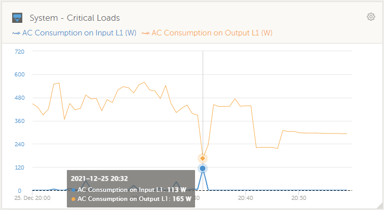
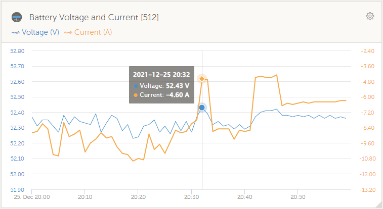
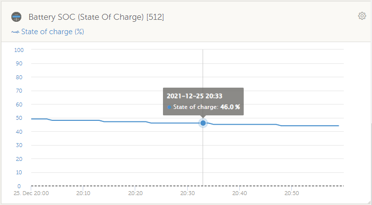
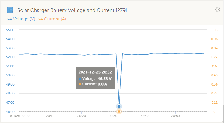
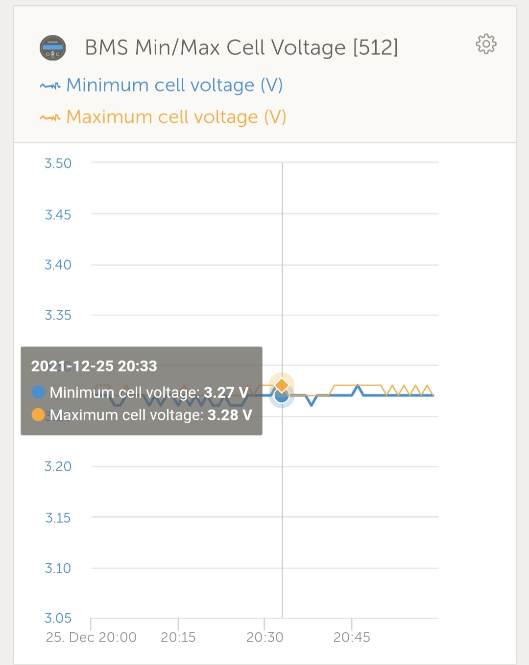
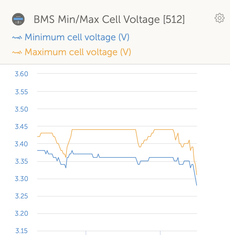
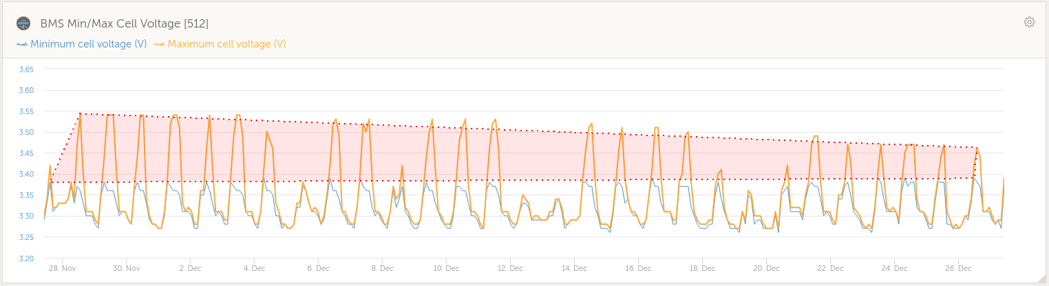
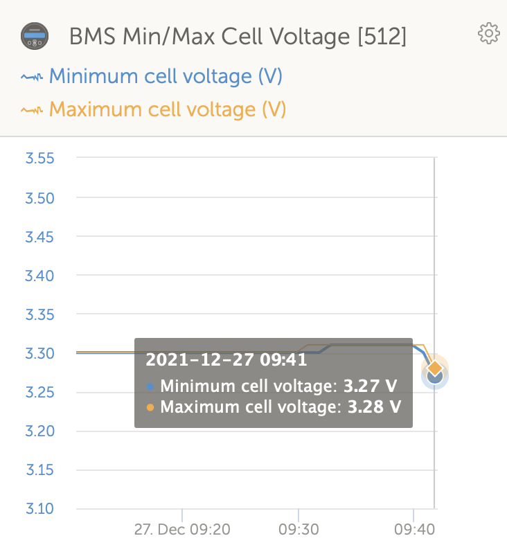
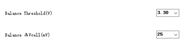
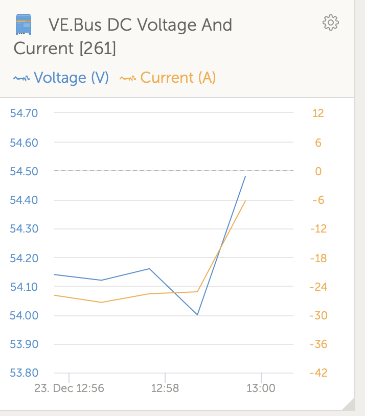
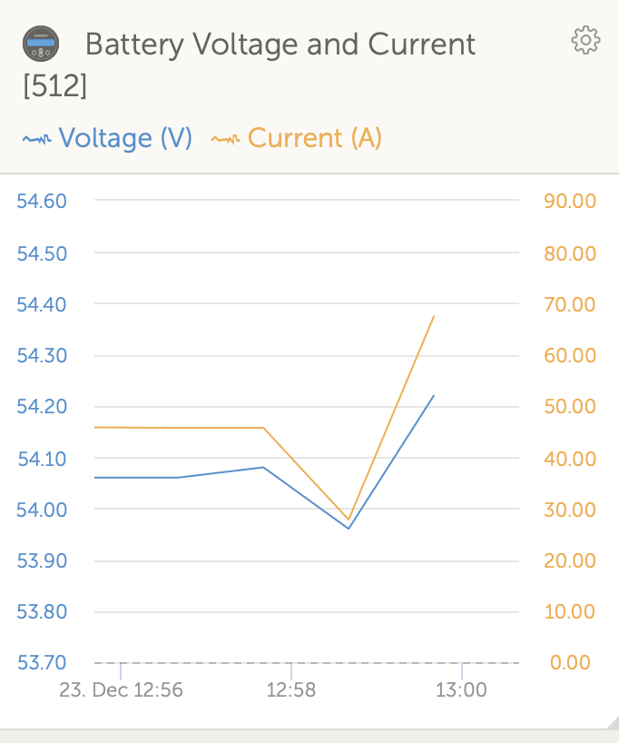
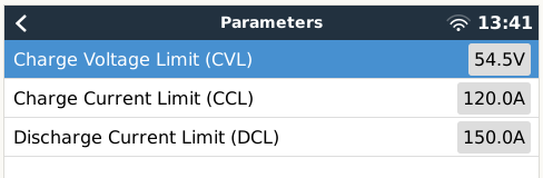
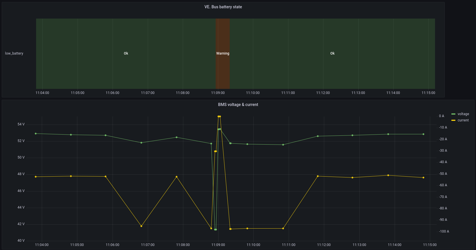
EDIT: I just realized that the MPPT reported a large drop in battery voltage - see the VRM screenshots I replied with. It shows a voltage drop to 46.58V, which is well below the 46.80V DC input low shut-down. I measured the voltage on the battery terminals and at the MPPT with a multimeter. The battery terminals currently measures 53.7V, while the MPPT battery terminals measure 53.9V. Does this seem okay?

My theory of the actual root cause:

- I've seen threads about similar issues, such as this one: MultiPlus II overload on grid failure. One comment that stood out:

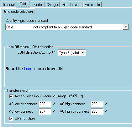
Hi. Solved a similar problem. If you have No grid code set please set you Ac low disconnect to 195vac of even 200ac....low reconnect from 202ac and above. Where i am in Zimbabwe my grid is above 240ac sometimes on failure it browns out as low as 170ac! Unless you install some external capacitors the Mp2 struggles to get into inverter mode from such a low voltage to raise it to 230! HENCE DC RIPPLE SHUTDOWNS..LOW BATTERY LIGHTS.and BMS SAFETY SWITCH OFF..etc.

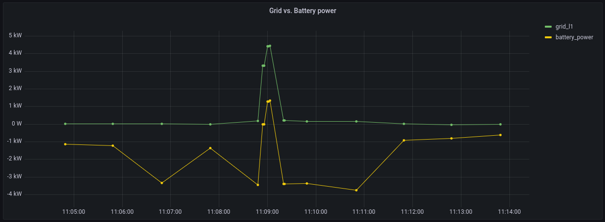
- I have a feeling that when the grid fails (often due to equipment failure) the grid actually experiences a brownout. Then the MP2 tries to follow the voltage down, and finally attempts to switch over to inverter mode, but now the voltage is low enough that it struggles to reach 230V, draws a large current on the battery (thus causing a voltage drop), and shuts off.

- The "AC low disconnect" is currently set at 200V, but maybe this is still too low. The grid runs at anything from 235V - 251V. Should I maybe set the low disconnect to 210V or even higher?

- An external energy meter is beings used via USB (ET112) on the Cerbo. Could it be that it is too slow, and when the grid browns out the MP2 actually follows the grid below the "AC low disconnect"?

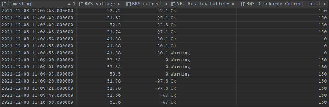
- I checked the BMS warning & alarm history via RS232 and PBMS Tools. There is only one alarm in the log since I purchased the battery, and that's when the "Low battery voltage" warning occurred without the system shutting down. The BMS reported a "SCP" protection (which I assume is Short Circuit Protection). Is this maybe due to a large current being drawn? There was about 4500W that was being drawn at that point, but the battery is 160AH @ 1C, so it should easily be able to handle that.

bms-scp.png


Does anyone have any ideas or suggestions? The installer has been on site multiple times and they can't figure it out, so I don't know. Should I maybe just insist that they replace the MP2 and battery?

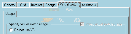
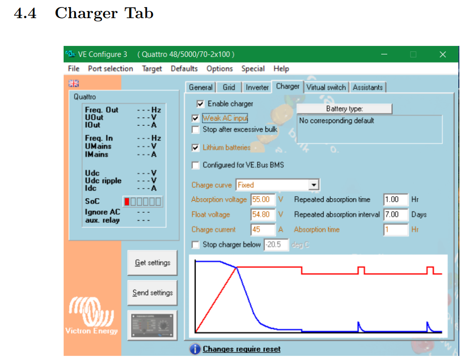
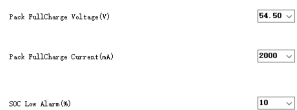
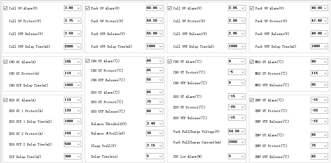
P.S. screenshots of system configuration to follow.

Multiplus-IILithium Batteryshutdown
bms-scp.png (6.8 KiB)
2 comments
2 |3000

Up to 8 attachments (including images) can be used with a maximum of 190.8 MiB each and 286.6 MiB total.

anrich avatar image anrich commented ·

Below is my system configuration:

general.png

grid.png

inverter.png

charger.png

virtual-switch.png

There is only one assistance, and that is the ESS assistant with the following config:

ess.png

0 Likes 0 ·
general.png (8.1 KiB)
grid.png (8.5 KiB)
inverter.png (23.2 KiB)
charger.png (15.8 KiB)
virtual-switch.png (5.0 KiB)
ess.png (14.5 KiB)
anrich avatar image anrich anrich commented ·

Here are a few charts from VRM:

At this point, the MP2 shuts off.

warnings-and-alarms.png

state.png

As you see here, the grid seems to have browned out just before the MP2 shut off. It's difficult to say exactly what happened since the VRM only logs every minute. I wish there was a way to record high frequency logs to local storage so it's easier to troubleshoot issues like these...

input-v-c.png

This is also quite strange, there was no load on AC loads (non-critical) when the grid failure occurred, but for some reason there's a spike (blue line). Is the MP2 maybe feeding back into the grid when it fails (due to its voltage being higher than the failing grid)? Could this maybe be causing the issue? The grid set-point is at 0W, and grid feed-in is disabled.

critical-loads.png

The BMS doesn't report a spike in current, but rather a reduction in current (makes sense since the MP2 shuts off).

bms-v-c.png

In this case the SoC was quite low, but this has happened at near 100% SoC as well.

bms-soc.png

This is very strange - the MPPT reports a large drop in battery voltage.

mppt-v-c.png

0 Likes 0 ·
state.png (15.7 KiB)
input-v-c.png (40.5 KiB)
critical-loads.png (35.1 KiB)
bms-v-c.png (43.5 KiB)
bms-soc.png (19.2 KiB)
mppt-v-c.png (29.4 KiB)
8 Answers
seb71 avatar image
seb71 answered ·

How many cells has your battery? 16? The voltages are not what I would set.


You should consider adding a voltage monitoring relay (preferably with a contactor) in your main electricity panel (so before AC-In of the inverter). And set that to 230V +/- 10% (if the nominal voltage is 230V in your area).


There was about 4500W that was being drawn at that point

Looks like in fact it was about 3400W. But if it was 4500W, that is above the maximum continuous power for that inverter. So in that case it was overloaded.

3 comments
2 |3000

Up to 8 attachments (including images) can be used with a maximum of 190.8 MiB each and 286.6 MiB total.

anrich avatar image anrich commented ·

Yes, it's a 16S battery. With the 46.80V "DC input low shut-down" that would mean a minimum of 2.925V per cell, which is quite low but still above what the cells are rated at (it seems). The battery technician said it's not an issue since the BMS will protect the battery.

These are the UV (under voltage) protection parameters on the BMS:

bms-params-cuv.png


You should consider adding a voltage monitoring relay

I see. I just want to make sure I understand the reason for the voltage monitoring relay: would this relay prevent a brownout from the reaching the MP2 in the first place? My guess is that it would then open the contactor as soon as it's outside of the 230V +/- 10% range, thus preventing the MP2 from having to deal with a brownout. Shouldn't the MP2 itself handle this with it's own internal relay (based on the "AC low disconnect")?


Looks like in fact it was about 3400W

Ah yes, I roughly correlated the BMS log entry timestamp to the VRM AC consumption, so I could be off (based on Pack Voltage and Current it is indeed 3400W). Sometimes the draw does go above 4000W, but at that point the MP2 shifts load to the grid to prevent overload (also depending on ambient temperature of course). I have seen a few overload warnings, but they only last a few seconds, at which point the MP2 starts drawing from the grid.

0 Likes 0 ·
bms-params-cuv.png (16.5 KiB)
seb71 avatar image seb71 anrich commented ·

the BMS will protect the battery

The BMS should be the last to act (preferably never). You want the battery discharge to be stopped primarily when a certain minimum SOC is reached. The second line of defense is the inverter shutdown (based on voltages) and the last line of defense is (should be) the BMS.


Yes, it's a 16S battery. With the 46.80V "DC input low shut-down" that would mean a minimum of 2.925V per cell, which is quite low but still above what the cells are rated at (it seems).

Wrong assumption. "x" battery voltage does not necessarily mean "x/16" cell voltage.
While such low cell voltages do not mean instant battery death, they will reduce the lifespan.

I would never allow any cell go below 3.0V (or above 3.6V). But it's your battery, your money.


Also you should make use of the "Dynamic cut-off voltages" from ESS settings. It does not make sense to set all voltage values the same value there.


I see. I just want to make sure I understand the reason for the voltage monitoring relay: would this relay prevent a brownout from the reaching the MP2 in the first place? My guess is that it would then open the contactor as soon as it's outside of the 230V +/- 10% range, thus preventing the MP2 from having to deal with a brownout. Shouldn't the MP2 itself handle this with it's own internal relay (based on the "AC low disconnect")?

For protection of your equipment (including the inverter).

0 Likes 0 ·
anrich avatar image anrich seb71 commented ·

I would never allow any cell go below 3.0V (or above 3.6V). But it's your battery, your money.

I fully agree, and I'd like to preserve the battery health as far as possible. The installer set the "DC input low shut-down" so low on recommendation from the battery supplier since they say there is a MP2 bug that causes incorrect shut off on a too high voltage. Can't find anything about such a bug though.

Also you should make use of the "Dynamic cut-off voltages" from ESS settings. It does not make sense to set all voltage values the same value there.

This setting is based on the battery's user manual. I also find it quite strange that all the values are the same, seems to defeat the purpose. This was set up by the installer.

bsl-ess.png

For protection of your equipment (including the inverter).

That makes sense. Do you have any recommendations on specific brands or models of voltage monitoring relays?

Also, I see the MPPT did report a large voltage drop when the inverter shut off. This wasn't reported on the MP2 / BMS. Do you know why that would be? Is it maybe the MPPT that is telling the inverter to shut down?

mppt-v-c.png

I used a multimeter to measure the battery at the terminals, as well as the MPPT at its terminals. The battery measures 53.7V and the MPPT measures 53.9V. It's currently busy charging the battery. Doesn't seem like there's a wiring (or wire gauge) issue.

0 Likes 0 ·
bsl-ess.png (91.8 KiB)
mppt-v-c.png (29.4 KiB)
seb71 avatar image
seb71 answered ·

Do you have any recommendations on specific brands or models of voltage monitoring relays?

I use a cheap Chinese relay (it was something like 15 USD). I do not use a contactor, but I got a relay rated for 63A, while the maximum I draw from grid is probably under 20A (and also the relay is protected by a 32A MCB). Also the grid is quite stable in my area so the relay rarely disconnects.

For large currents and/or frequent disconnects you must also use a contactor.

You can pair the same cheap Chinese relay with a good contactor (rated above your maximum current draw), or you can get a more expensive voltage monitoring relay from manufacturers like Finder, for instance (these types always require a contactor).


Also, I see the MPPT did report a large voltage drop when the inverter shut off. This wasn't reported on the MP2 / BMS. Do you know why that would be? Is it maybe the MPPT that is telling the inverter to shut down?

The low battery voltage was the one which caused the inverter shutdown. Not the MPPT.

Doesn't seem like there's a wiring (or wire gauge) issue.

Yeah, about that: I meant to, but I forgot to ask what wire gauge are your inverter wires.

Also do you have busbars for connecting everything to the battery?

2 comments
2 |3000

Up to 8 attachments (including images) can be used with a maximum of 190.8 MiB each and 286.6 MiB total.

anrich avatar image anrich commented ·

Excellent, thanks for the info on the relay. I'll have a search around to see what's available locally and what the costs are.

The low battery voltage was the one which caused the inverter shutdown. Not the MPPT.

Makes sense. I just wonder if it is in fact a brownout that is causing the low battery voltage, or is something else wrong. Could it be that a relay in the MP2 isn't working correctly? I don't know what to do to narrow down the problem.

what wire gauge are your inverter wires

The AC-IN and AC-OUT wires look about 6mm.

All the DC wires look about 12mm. Here is a photo of the negative busbar where everything connects to the battery:

20211226-123338.jpg

0 Likes 0 ·
anrich avatar image anrich anrich commented ·

Here is a photo of the AC in and out wires:

20211226-123546.jpg

0 Likes 0 ·
seb71 avatar image
seb71 answered ·

Makes sense. I just wonder if it is in fact a brownout that is causing the low battery voltage, or is something else wrong. Could it be that a relay in the MP2 isn't working correctly? I don't know what to do to narrow down the problem.

Your inverter is set to shutdown at 47V (battery voltage). According to that MPPT log, the battery voltage dropped down under 47V (46.58V).

Here is a photo of the negative busbar where everything connects to the battery:

That's not a busbar. It's a bolt with multiple wire lugs on it. I would replace that with proper copper busbars.

All the DC wires look about 12mm.

That is the wire diameter including the insulation? The wire could be only 35mm2 in that case. If you have no other way to find out, check the wire lugs. They should have some markings for the wire size and bolt diameter.

If you check the inverter manual, the recommended cross section is 70mm2 (for lengths under 5m).

19 comments
2 |3000

Up to 8 attachments (including images) can be used with a maximum of 190.8 MiB each and 286.6 MiB total.

anrich avatar image anrich commented ·
According to that MPPT log, the battery voltage dropped down under 47V (46.58V)

That makes sense that it would shut off at such a low voltage. The question is, why did the voltage of the battery drop so low? The load on the system at the time of shut off was at most 600W from what I can see. Also, why didn't this low voltage cause an alarm on the inverter or the BMS? It's strange to me that the inverter shut off without an alarm being raised (just a warning).

I would replace that with proper copper busbars.

Noted, thank you. I'll see if I can replace the bolts with copper busbars. Could using a bolt cause a voltage drop when the grid fails, or is this just a general recommendation?

If you check the inverter manual, the recommended cross section is 70mm2 (for lengths under 5m).

I measured one of the wires (removed the insulation tape at a bolt) and it's at least 10mm in diameter, but closer to 12mm (without insulation). Thus it's at least ~78mm² cross section, but more likely close to or more than 100mm²


0 Likes 0 ·
seb71 avatar image seb71 anrich commented ·
Apparently the battery voltage actually dropped that low (two devices measured similar values).

A 160Ah LiFePO4 should be able to take those loads, so I am not sure why it happens.

-------

Maybe make some tests with various loads (from low to high). Turn off AC In and disconnect the PV array, so that all power comes only from the battery.

Measure (with a good multimeter) the DC voltage at the inverter battery posts (where the battery wires are connected inside the inverter) and directly at the battery terminals.

Check to see if there is a significant difference between those two measurements - at the inverter and at the battery - under constant load. If there is, you have a problem with the wiring between the battery and the inverter or some bad contact.

And also check how much the battery voltage drops under increasingly higher loads. There might be something wrong with your battery (or a cell inside it).


Make the tests above with a full battery, then with a partially discharged battery (~50%) and then with a battery at 15% SOC or so.


If you have a way to check or measure individual cell voltages, those are more important than battery voltage.

0 Likes 0 ·
anrich avatar image anrich seb71 commented ·
Okay great thank you, I'll try to do some testing this coming week.


What would you say is an unacceptable difference in voltage between the battery poles and inverter battery connection? Is this something I can find in documentation somewhere?

I'll also record the individual cell voltages as reported by the BMS (I can access these via a direct serial connection to the battery). Unfortunately I cannot read the cells directly with a multimeter as I don't want to open the battery (outside my comfort zone, and will void warranty).


Lastly, since this only happens when there is a grid outage, do you think my theory of the inverter following the grid to a too low voltage could be valid? Or could it be that the inverter is feeding back to the grid when the grid supply fails, i.e. the relevant inverter relay isn't acting fast enough? I'm asking because I'm still considering increasing the minimum disconnect voltage to around 210V to see if that helps when a brown out occurs.

0 Likes 0 ·
marekp avatar image marekp seb71 commented ·
@anrich

I would suggest also to measure voltage drop on the positive wire between plus terminal on the battery and plus terminal on MP-II. Same with the minus wire.

Measuring voltage drop this way is more accurate.

0 Likes 0 ·
anrich avatar image anrich marekp commented ·
Thank you, I did not even consider testing that way. I'll record this as well at different constant loads and SoC. Hopefully I'll have some data in a day or two.


The unfortunate part is that the issue only seems to occur when the grid fails, which leads me to believe the way in which the grid fails (and maybe a high impedence to the grid) is causing the problem, but I really don't know. I can manually switch off from the grid and there's no inverter shut off or low voltage issue.

0 Likes 0 ·
nickdb avatar image nickdb ♦♦ anrich commented ·

@anrich from another thread, I know you have the same model I do, with it's known BMS issues.

You should look over the week or so, in the run-up to these shutdown events: what the battery voltage is doing over the period - is it trending down even though it is reporting fully charged?

Is the battery still charging at high rates when the SOC is around 98%-100%?

You may well be in a pattern where the battery is erroneously reporting a full SOC but it is actually well below.

You will see this in regular spikes of SOC during solar charging, usually 20 to 40% increments.

The SOC reported also seems to erroneously increase at an accelerated rate compared to the actual SOC.

This is something that breaks ESS quite nicely.

I would eliminate this as an underlying cause.

0 Likes 0 ·
anrich avatar image anrich nickdb ♦♦ commented ·

Hi Nick,


So a battery technician from the supplier was on site. The technician looked over the battery parameters and BMS logs, and stated that everything looks fine. I explained that the SoC sometimes jumps and the battery sometimes still takes a large charge current when 100% SoC is reached. He stated that this is completely normal, and that the BMS will dynamically adjust SoC as it "learns" the typical voltage range of the pack. He stated that it will normalize over time, especially as cells are being balanced (since it's passive balancing it takes long). I mentioned that 1.07 of the firmware seems to have issues, he denied this and said it's more likely a Victron bug whereby the low voltage disconnect is erroneously triggered (he mentioned that he believes there's a bug with an offset somewhere that affects BSL and FreedomWon specifically).

I honestly don't know what to believe anymore though.

0 Likes 0 ·
nickdb avatar image nickdb ♦♦ anrich commented ·

Complete bulldust I am afraid to say.

The BMS will learn zilch.

Sure cell balancing can take a while, mine did.

I am hoping for progress early in the new year or I will be swapping them for another model.

Would suggest the victron bug is also a myth, mine have no issues with the multplus, but with a SOC that is complete fiction the environment will not work properly.

If I did not actively manage my SOC I would also run the batteries flat and hit low voltage levels.

My system will run the batteries down to 30%. On a bad day with high usage/low PV they may only charge to 60% (can calculate from the cell voltages) but it reports 100% for most of the day. Now if ESS lets it discharge to 30% you can see the problem.

Left unattended the problem compounds over multiple days,

0 Likes 0 ·
anrich avatar image anrich nickdb ♦♦ commented ·

That's disheartening, but thanks for the info. What I'm going to do is to monitor (every few hours) cell voltages (via RS232 to BMS using PBMS tools) to see how that corresponds with SoC. Also going to monitor voltage at the battery terminals. I'll also still investigate potential voltage drops throughout the system at different loads using a multimeter.

I have some questions, would really appreciate input:

1. Am I correct to assume that 100% SoC should be 54.5V for the pack, and thus 3.4V per cell? Of course this assumes no or very low load.

2. How are you "actively managing" your SoC? Do you just manually increase the minimum SoC on ESS if you measure the actual voltages (with a multimeter I assume) to be lower than what the SoC from the BMS indicates it should be?

0 Likes 0 ·
anrich avatar image anrich anrich commented ·
One thing that I should point out makes no sense to me: if the BMS is reporting SoC completely incorrectly, why does the battery run perfectly for hours after the inverter restart issue? And this is without PV, and not on unreasonably low voltages.


So take the VRM charts posted originally. The grid fails, the battery voltage drops (according to MPPT chart and low battery voltage warning), the inverter shuts off, then after a minute it restarts. After that it ran fine for hours and hours (until SoC reached my 30% minimum setpoint, and luckily by then the grid was back online).
0 Likes 0 ·
anrich avatar image anrich anrich commented ·

Does this then also mean that the BMS is reporting minimum and maximum cell voltages incorrectly? This was the min & max cell voltage at the moment the grid failed, and low battery voltage warning occurred and the inverter shuts down:

screenshot-20211226-213057-chrome.jpg

0 Likes 0 ·
nickdb avatar image nickdb ♦♦ anrich commented ·

BSL run cells lower than others, so you are right 3.4V is their target voltage. It is one of the nice things about them and offers a good battery life. I have not seen any issues with min/max voltages reported so if you are seeing this at the end of charge, when the battery goes to idle then the battery will be fully charged.

In my case the SOC is at 100% but the voltages are lower and it is still charging at 2000W-3000W or more.

I either change ESS modes to keep charged - this will also show if the battery is fully charged or not, or I raise the minimum SOC.

That you can get the battery to work fine after a reset is odd, if there was a big spike in load at cutover, this could draw the battery down beneath a threshold. Unfortunately VRM isn't granular enough to catch this, you would need grafana to capture something more detailed.

I have 2 packs in my setup, apart from the SOC and delays in resolving it, they are decent batteries. I am kicking myself for not originally choosing the 120AH instead. If there was a way to get me your details I could keep you in the loop of my progress.

Just to add, the balancing is quite slow but it works, mine took a while to narrow the min/max.

screenshot-2021-12-27-at-091250.png

0 Likes 0 ·
anrich avatar image anrich nickdb ♦♦ commented ·

Note: I tried to include a temporary email address to share contact details privately, but now that reply is "in moderation" (guess it's not allowed to include email addresses in messages, so don't know how to share contact details privately, since these forums don't seem to have direct message functionality).

----

I see thank you. Isn't there maybe a way to completely "bypass" the reported SoC, and let the Cerbo / multi just use the voltage to calculate SoC? I'm wondering if an ESS assistant can't maybe do this... Maybe an assistant can just periodically change the min SoC based on voltage.

I have also seen mine take 2000W+ at a reported 100% SoC, so that behaviour definitely matches.

Yeah VRM's low logging frequency is quite a pain. I'm planning to purchase a raspberry PI (really want a PI 4 with 8GB ram though, and stock is impossible to find). I then want to log BMS data directly to the PI (as fast as the RS232 serial allows), and then plot on grafana or similar. This could maybe capture a voltage drop where VRM would have missed it.

Yeah, I'm actually considering negotiating with my installer to replace this 160Ah with 2 x 120Ah. Obviously I'll have to pay up, but at this point if the issue can't be figured out, replacing things is the only option I see.

So I can actually see the balancing work over time, here's the last 30 days of min & max cell voltages (I added the overlay to make it more clear) The battery has roughly 40 cycles on it.

mix-max-overlay.png

0 Likes 0 ·
mix-max-overlay.png (93.2 KiB)
Show more comments
anrich avatar image anrich nickdb ♦♦ commented ·

I see thank you. Isn't there maybe a way to completely "bypass" the reported SoC, and let the Cerbo / multi just use the voltage to calculate SoC? I'm wondering if an ESS assistant can't maybe do this... Maybe an assistant can just periodically change the min SoC based on voltage.

I have also seen mine take 2000W+ at a reported 100% SoC, so that behaviour definitely matches.

Yeah VRM's low logging frequency is quite a pain. I'm planning to purchase a raspberry PI (really want a PI 4 with 8GB ram though, and stock is impossible to find). I then want to log BMS data directly to the PI (as fast as the RS232 serial allows), and then plot on grafana or similar. This could maybe capture a voltage drop where VRM would have missed it.

Yeah, I'm actually considering negotiating with my installer to replace this 160Ah with 2 x 120Ah. Obviously I'll have to pay up, but at this point if the issue can't be figured out, replacing things is the only option I see.

Hmm, doesn't seem like these forums support direct messaging. It'd be great to stay in contact since I can maybe help you troubleshoot / debug. Easiest is probably a disposable email address so I don't have to give out my actual contact details here. You can mail at: dorrance@ijointeract.com (it's a disposable address which I'll delete after receiving your mail). If you have another way to share details privately, please let me know.

So I can actually see the balancing work over time, here's the last 30 days of min & max cell voltages (I added the overlay to make it more clear) The battery has roughly 40 cycles on it.

mix-max-overlay.png

0 Likes 0 ·
mix-max-overlay.png (93.2 KiB)
Show more comments
nickdb avatar image nickdb ♦♦ anrich commented ·

For comparison purposes. This chart is in the morning around 44% SOC, idle house loads with a small amount of solar going into the batteries. I then add a 2000W load. I have twice the packs so a single pack would have more to deal with but that's still way away from any low battery limits.


screenshot-2021-12-27-at-094323.png

0 Likes 0 ·
anrich avatar image anrich nickdb ♦♦ commented ·

Interesting thanks. So I actually loaded the battery heavily (0.5C, ~4000W) this morning on about 31% SoC, and everything looks fine to me:

low-soc-load.png

Note after this I opted to bump the min SoC to 60% (charging from grid) since it's rainy, and I'm preparing to start voltage drop testing at varying SoC and load.

0 Likes 0 ·
low-soc-load.png (100.1 KiB)
Show more comments
seb71 avatar image
seb71 answered ·

Am I correct to assume that 100% SoC should be 54.5V for the pack, and thus 3.4V per cell?

Not quite. Check the battery manufacturer specs, but usually 100% SOC is around 3.6V cell voltage (for LiFePO4). This does not mean you have to choose this voltage level as 100% SOC. Between 3.45V and 3.6V there is very little energy and the voltage increases quickly when charging. If there is any manufacturing or charge difference between cells, there is a risk that some cell(s) will rise above 3.6V. A BMS should stop charging before that happens.

So, in order to avoid getting into potentially dangerous territory when charging, you can "decide" that 100% corresponds to 3.50V or to 3.55V. Or even 3.40V. But the battery manufacturer rated the capacity when discharged from 3.6V (for instance), so you might not get the full rated capacity (but not by much). On the other hand, you will get a longer battery life.

Another factor to consider: the cell balancing done by BMS happens when the cells/battery are close to full. You must check if you reach those voltage levels. Could be above 3.50V for instance. Or maybe you can adjust it. I don't know your BMS.

17 comments
2 |3000

Up to 8 attachments (including images) can be used with a maximum of 190.8 MiB each and 286.6 MiB total.

anrich avatar image anrich commented ·

Thank you for the explanation. As @nickdb pointed out, these batteries operate at a lower cell voltage than the average LFP. They target about 3.4V per cell - you can also see the balancing targeting this in one of my reply's above. I am thus quite certain that balancing is working correctly. It is taking very long though, but that's to be expected for passive cell balancing as far as I understand.

The BMS is configured (from the supplier) to start balancing at a voltage of 3.30V, and it balances at 25mV:

screenshot-from-2021-12-27-10-39-58.png

0 Likes 0 ·
seb71 avatar image seb71 anrich commented ·
Well, as long as they are LiFePO4, it's unlikely to be that different.

The manufacturer might limit the charging voltage to 3.40V to get a longer battery life (at slight capacity reduction).

But starting balancing at 3.30V is a curious decision. That voltage is clearly in the flat zone of the LiFePO4 charging curve. When using a BMS, you want the cells to have the same voltage at the top - that is the main target. Then, if the cells are well matched, you will have very close cell voltages from full to empty. If not, you have to rise the battery cut off voltage based on the voltage of the weakest cell.

--------

In your first posts you never spoke about SOC value "jumps". You mentioned something about that much later. Can you elaborate on that?

If the battery BMS erroneously reports the SOC, maybe you could "fix" that by adding a SmartShunt to your system. But I am not sure if you can still set the Cerbo to use the SmartShunt as the SOC monitoring device when the battery has a BMS which also communicates with the Cerbo.

0 Likes 0 ·
nickdb avatar image nickdb ♦♦ seb71 commented ·

Shunts are horrid things, I was pleased to remove mine.

For background info:

This is a new model of battery with a new BMS/firmware combination.

The SOC behaviour was introduced after a code update yet the battery manufacturer and the BMS supplier are scratching their heads, we have a plan to tackle this in the new year and hopefully fix it.

The issue above may be unrelated but if you have an unreliable SOC then problems can cascade from there.

If you look at the pics below from my install, you will see two things. One - very steep charge curves and (Two) vertical jumps in SOC.

The BMS is overestimating the amount of charge and then also leaping up in large increments.

screenshot-2021-12-27-at-120334.png

Here is a detailed view of one day where the SOC jumps from 63% to 93% in minutes (and it gets worse than that).screenshot-2021-12-27-at-120818.png

The upshot is you need to be aware, until this is fixed, that you need to rely on battery voltage not SOC. If you aren't paying attention, or are an end-user, then you may have no clue this is happening.

As an aside. I believe this battery is actually 32 cells - 16 banks of 2 parallel cells, unless it was explained to me incorrectly.

0 Likes 0 ·
seb71 avatar image seb71 nickdb ♦♦ commented ·

The SOC graph is strange when charging, but how does the battery voltage and current looks for the same time frame? Do you see the same jumps there?

What's the battery capacity (and nominal voltage)?

How large is the PV array (assuming you do not charge from the grid)?


As an aside. I believe this battery is actually 32 cells - 16 banks of 2 parallel cells, unless it was explained to me incorrectly.

If that's the case, then the BMS monitors and balances each pair of cells in parallel as a single cell. This might lead to issues over time, if the cells are not well matched in capacity and internal resistance.

Can you see voltages for each cell (not only lowest and highest cell voltage from the battery pack)?


Edit:
Removed a dumb part. :)

0 Likes 0 ·
nickdb avatar image nickdb ♦♦ seb71 commented ·

Without the battery software I can't see each cell, I need to get my hands on the cable and battery software.

As mentioned lower down, the jump coincides with a transition from higher to lower charge to the battery. See charts.


screenshot-2021-12-27-at-130228.png

screenshot-2021-12-27-at-130233.png

I have 320AH (2 packs) and charge off around 4200W of PV (roof constraints).

Nominal voltage is 51.2V


0 Likes 0 ·
anrich avatar image anrich nickdb ♦♦ commented ·

I have access to a cable and the software (@nickdb - I can help with this if we can make direct contact). Here is a screenshot showing 16 cells I took a few weeks ago:

bms-cells.png

0 Likes 0 ·
bms-cells.png (56.0 KiB)
marekp avatar image marekp nickdb ♦♦ commented ·

@nickdb

In my installation this, as you call it, "upshot" was happening when BMS told MP-II to stop charging. After that signal, system assumes that battery is full and SOC was set to over 90%.

0 Likes 0 ·
nickdb avatar image nickdb ♦♦ marekp commented ·
The "jumps" tend to coincide (but not always) to moments when PV transitions from a high amount of charge power to low (cloud for example) or when a larger load is applied, which diverts PV from charging to supplying AC.

This transition seems to trigger the jump, with an associated drop in the DC bus voltage, which is expected.

I suspect a BMS bug which is being triggered by this drop in charge.

0 Likes 0 ·
seb71 avatar image seb71 marekp commented ·

If it works like that, then a single battery cell with a much higher voltage than the rest of the cells can trigger a big jump in SOC.

And the OP does have big voltage differences between cells at the top (more than 0.1V).

If the SOC "synchronization" can't be adjusted by the user, limiting the charging current should improve this (BMS has more time to balance the cells). If then after a while the cells gets closer in voltage at the top, the charging current limit can be increased.

0 Likes 0 ·
anrich avatar image anrich nickdb ♦♦ commented ·

@nickdb When you say:

The SOC behaviour was introduced after a code update yet the battery manufacturer and the BMS supplier are scratching their heads, we have a plan to tackle this in the new year and hopefully fix it.

Have you been in contact with "Wisdom Industrial Power Technology" (I believe they manufacture BSL)? I'd love to somehow place my installer in contact with them so they can get the info directly from the source. My installer buys their equipment from a large importer / supplier. It's this importer who sent out a battery technician, and he knew nothing about any BMS bug in 1.07.

You also mention you have a plan to tackle this in the new year - can you share any details?

0 Likes 0 ·
nickdb avatar image nickdb ♦♦ anrich commented ·

I am having to work through the local importer, who are the middle man.

I have tried contacting @BSLBATT Lithium directly and they ignore requests or just redirect you back to the importer.

It has been frustrating.

I provided access to them via VRM but this wasn't sufficient apparently.

We are now having to install a CAN bus reader to capture battery telemetry to try identify what might be causing this.

To be fair to all involved, there are time zone and language issues dealing with each other which complicates matters.

@anrich I have added an email contact in my profile summary.

0 Likes 0 ·
klim8skeptic avatar image klim8skeptic ♦ nickdb ♦♦ commented ·

A manufacturer that does not supply Data for their batteries should not be supported, or recommended.

Most of the Data links go nowhere useful.

0 Likes 0 ·
nickdb avatar image nickdb ♦♦ klim8skeptic ♦ commented ·

They seem to build to spec for importers, there is data, just nowhere you or I could easily access it - I have looked.

My impression is it probably needed a bit more testing, the 120AH has been out for some time and has a good reputation and decent cost/kWh.

It's all part of the experience dealing with Asian manufacturing, but incredibly painful when there are problems.

If there was local stock, I would have exchanged them already.

Worth noting, as I understand it, it is the importer which did all the testing with Victron.

0 Likes 0 ·
klim8skeptic avatar image klim8skeptic ♦ nickdb ♦♦ commented ·

It's all part of the experience dealing with Asian manufacturing, but incredibly painful when there are problems.

The fact is that every data sheet you see, shows exactly the same data is a big problem.

The fact that the manufacturers published data does not match up to the recommended charge data poses an extra warranty problem.

Wonder what the cell manufacturers think of their product being mis-represented?

0 Likes 0 ·
nickdb avatar image nickdb ♦♦ klim8skeptic ♦ commented ·

Not sure I follow.

The cells will come from the usual suspects, each will have an operating range (upper, lower, recommended) and associated performance, life etc.

I'm not buying cells, I don't even know whose are in the box.

If the supplier wants to pick a specific operating level, that's their business, as long as they don't set fire to the house and honour their product warranty.

I am struggling to see the harm in a supplier that chooses to run conservatively, vs one that pushes the limits.

Was under the impression that when it comes to pushing batteries, less is more.

It's always a trade off.

0 Likes 0 ·
klim8skeptic avatar image klim8skeptic ♦ nickdb ♦♦ commented ·

The cells will come from the usual suspects, each will have an operating range (upper, lower, recommended) and associated performance, life etc.

Now you are getting it, Cell manufacturers give a 12 month warranty (?) should you adhere to their recommendations.

Battery manufacturers are giving 10 years warranty, should you follow their obscure/deceitful recommendations,

I have simply recommended the OP should follow the published data.

Nothing more than that.

0 Likes 0 ·
anrich avatar image anrich nickdb ♦♦ commented ·
I see, thanks. Working through a middleman is always a hassle. Thanks for sharing your email - I have it so you can remove again if you want to. I'll email you soon.
0 Likes 0 ·
klim8skeptic avatar image
klim8skeptic answered ·

Personally I think the OP should review their charging setpoints based upon the document revealed in their other thread. BSL B-LFP48-160E , 51.2v 160Ah battery.

Looking closely at that document, the recommended charge voltage is 56v, very standard cell voltage of 3.5v. Looking closely at the graphs in that document, BSL are charging the battery to over 57 volts.

The details from Victron Energy may not be current, or even related to the OP's battery model. I mean who knows? They are not dated, revision numbers, or even battery model numbers on the PDF's specification data.

According to BSL promotional material , BSL use BYD and CATL cells in their packaged batteries. Once again very standard cells that respond to standard Lifepo4 charging strategies / voltages.

Not my batteries, so not my problem.

7 comments
2 |3000

Up to 8 attachments (including images) can be used with a maximum of 190.8 MiB each and 286.6 MiB total.

nickdb avatar image nickdb ♦♦ commented ·

The battery guide sets the manual limit at 55V, not 56V.

The BMS sets the setpoint at 54.5V regardless, which is what the multi/mppts will target.

This is from the latest document (not on the victron site) and is identical to the rest of the range.

BSL - User Manual - 51.2v 160Ah CANBUS.pdf

0 Likes 0 ·
klim8skeptic avatar image klim8skeptic ♦ nickdb ♦♦ commented ·

Manufacturers PDF recommends 55v to 56v. Also shows charging voltage (in graphs) to over 57 volts.

0 Likes 0 ·
nickdb avatar image nickdb ♦♦ klim8skeptic ♦ commented ·

post edited to include the current doc.

Edited. It's worth noting what the battery can do vs what the tested victron settings are, are two different things. If you want your warranties honoured, best to stick to the script.

0 Likes 0 ·
anrich avatar image anrich commented ·

This is the Victron guide for my battery mode: bsl-user-manual-512v-160ah-canbus.pdf (the one that you linked is for a different model).

When you say:

OP should review their charging setpoints

Which specific config are you referring to?

According to the manual I linked above (3.2):

screenshot-from-2021-12-27-13-42-43.png

The thing is, those parameters seem to come from the BMS, and aren't configurable by the user. On the remote console when navigating to the battery:

screenshot-from-2021-12-27-13-41-48.png

I cannot change these (i.e. clicking on them doesn't reveal an edit box or "+" / "-" buttons). It's also clear that the CCL and DCL doesn't even correspond with what the documentation says.

In terms of VE. Configure charger config, my settings correspond to the guide. The guide shows:

screenshot-from-2021-12-27-13-46-23.png

This corresponds to my config. My charge current limit is just set a bit lower (35A), but I don't see that causing problems.

On the BMS software I can also see (Pack FullCharge Voltage):

screenshot-from-2021-12-27-13-51-35.png


Am I maybe missing something somewhere?

0 Likes 0 ·
nickdb avatar image nickdb ♦♦ anrich commented ·
You're not missing anything. The system is configured as per manufacturers supported Victron configuration, and yes, the BMS pretty much sets the operational parameters.

There is nothing here you can tweak which could change the behaviour you're seeing.

You will achieve nothing running the system beyond the user guide, apart from risking your warranties. Leave the "overclocking" to the DIY enthusiasts.

0 Likes 0 ·
klim8skeptic avatar image klim8skeptic ♦ anrich commented ·

Am I maybe missing something somewhere?

There is a discrepancy between the published data, and the recommended settings that is hard to overlook.

You dont have "special" low voltage cells, just special directions to follow to meet manufacturers warranty directives.

@nickdb 3.5v per cell is pretty much standard for a Lifepo4 cell.

0 Likes 0 ·
nickdb avatar image nickdb ♦♦ klim8skeptic ♦ commented ·

Agreed. In the same way Pylon run 15 instead of 16 cells, BSL run their cells lower than convention, I guess this is about life span. They offer 160A discharge per pack which isn't bad, but I suspect they would become toasters if you tried to sustain this.

Bottom line, the manufacturer chooses the specs for the given capacity and battery life. That we could tune it and push it harder is mainly academic but if for whatever reason you wanted to claim against warranty, they would be within their rights to show you the middle finger.

It is easy to promise a long battery life, it is harder to actually do it.

It is worth remembering that the different ESS modes will also use different charge limits - keep batteries charged for example will run higher.

Personally I couldn't care less what a cell runs at, it just needs to deliver on charge/discharge rates and make its promised life.

0 Likes 0 ·
anrich avatar image
anrich answered ·

Update 2021/12/28

I had a great conversation with @nickdb yesterday and he mentioned there's a "Venus OS large" image for GX devices that could be useful for troubleshooting (specifically to get more granular log data into Grafana - the 1 minute log interval in VRM isn't sufficient). I did some research and then realised I don't even need another image, I could simply setup MQTT to send data to my own hosted Grafana.

I am going to do this, but the idea got me thinking - what if I export the data from VRM and explore it in more depth elsewhere. I exported the data as CSV, and imported into a PostgreSQL DB (simply because I know postgres well). I did some exploration and made some potentially interesting findings. I also setup a Grafana on top of postgres to visualise the findings.

I'm not sure what to make of this, if anyone has any ideas and comments would be appreciated.

Findings

After the installer reduced the "DC input low shut-down" to 46.80V (on recommendation from the supplier based on an alleged "Multiplus-ii voltage offset bug") there was one occurrence of a "Low battery" warning, but the system did not shut down, and there was no grid failure at the time (there could have been a brownout, but it's not apparent in the data).

Here you can see the low battery warning occur, as well as the battery voltage and current as reported by the BMS.

screenshot-from-2021-12-28-15-36-24.png

  • At 11:08:48 97A is being drawn from the battery
  • At 11:08:54 the voltage drops to 41.4V (This is obviously a problem)
    • The current being drawn from the battery then decreases.
  • At 11:08:56 the "Low battery" warning starts.

Exploring the data some more, I also discovered that the "Discharge Current Limit (DCL)" as reported by the BMS dropped from 150A to 0A at 11:08:54.

screenshot-from-2021-12-28-15-57-28.png

The drop in Discharge Current Limit also corresponds with the time of the "SCP Protect" log entry I found on the BMS. I believe this is Short Circuit Protection.

Furthermore, you can see the multi hand over to the grid (since the BMS is preventing discharge from the battery):

screenshot-from-2021-12-28-16-50-02.png

What this tells me (please let me know if you disagree):

  • The battery voltage is definitely dropping below acceptable levels (it isn't a false warning).
  • The BMS protection is activating to protect the battery.
  • This causes the low battery warning.
  • I believe the multi didn't shut off in this case because the grid was available and it could hand over the load to the grid quickly enough.

What remains to be answered:

  • What is causing such a large draw (or even potentially a short circuit) on the battery?
  • Why does it mostly happen when the grid fails?

Some of my theories:

  • During my conversation with Nick yesterday, he mentioned that this could be as simple as a faulty multiplus-ii. Maybe the multi is somehow causing a short circuit / very high load on the battery for no apparent reason.
  • Could it be that the BMS is somehow causing a short circuit inside the battery?
  • Could it be an appliance in my house that is causing a massive load spike / short? I doubt this because I have breakers on everything, and all appliances are working fine.
  • Could it be something that is wrong with the grid itself that is causing a massive current pull on my AC input?
  • Could this actually be a firmware bug somewhere (either BMS or multi)? This is starting to seem less and less likely.

Any comments would be much appreciated, thanks!


2 |3000

Up to 8 attachments (including images) can be used with a maximum of 190.8 MiB each and 286.6 MiB total.

nedee avatar image
nedee answered ·

Any update on this issue? I experience exactly the same on MPii 10KW and 2x Stubbys. Despite only 150W load at the time loadshedding starts, MP shuts down showing low battery error also the GX Touch goes down… everything restarts after a minute (this is at night with no PV feeding in). In contrast when the main CB is thrown, it never shuts down. Must be that the brown-out effect of grid failure plays a role….

2 comments
2 |3000

Up to 8 attachments (including images) can be used with a maximum of 190.8 MiB each and 286.6 MiB total.

nickdb avatar image nickdb ♦♦ commented ·
The OP has had the packs updated by the supplier - new firmware amongst other things.

It is currently being tested to see if the issue is resolved.


0 Likes 0 ·
nedee avatar image nedee nickdb ♦♦ commented ·
Thanks @nickdb

@anrich, will be grateful for feedback when you are ready
0 Likes 0 ·
shadz avatar image
shadz answered ·

Hi, did you manage to resolve this? i have a similar issue

8 comments
2 |3000

Up to 8 attachments (including images) can be used with a maximum of 190.8 MiB each and 286.6 MiB total.

nickdb avatar image nickdb ♦♦ commented ·
It was a battery issue. Resolved with undisclosed BMS changes.
0 Likes 0 ·
insanesplash avatar image insanesplash nickdb ♦♦ commented ·

I am running version 3.04 on my 6.4Kwh BSL Batteries (2) connected to a MP2 10k with the same issues. The 2 batteries were used in a different part of the country with a MP 5K with out any issues. So far it seems to only happen in the evening vs the morning loadshedding slots in Cape Town.


Interestingly, I had a MP2 GX 5K which was having issues, and eventually had it replaced due to a ground relay fault and since then, its been working without any issues. The replacement also runs the latest Victron firmware of v502. Both inverters are within 5kms of each other on the same grid. (This seems to be an issue only in Cape Town?)


What version of Firmware are you running and what is your BMS middle code?

Did you make any changes to the battery parameters within the BMS, if so what did you adjust away from the factory settings?


0 Likes 0 ·
insanesplash avatar image insanesplash insanesplash commented ·

Here are the current defaults:


capture1.png

0 Likes 0 ·
capture1.png (34.5 KiB)
nickdb avatar image nickdb ♦♦ insanesplash commented ·
What is the dcl they are reporting to the GX - 180A? Thats a bit light in the pants for 10kVA and will struggle with a brownout.

There is nothing you can tweak in the BMS. Only the importer can help you, you need to get a support case open with them.

Good luck.


0 Likes 0 ·
insanesplash avatar image insanesplash nickdb ♦♦ commented ·
DCL is 200A (100A per battery).

Ill reach out to GOG and ask. (I do have access to the BMS)

0 Likes 0 ·
nickdb avatar image nickdb ♦♦ insanesplash commented ·

200A is tight for that 10kVA, it can surge beyond that and unfortunately these Pace BMS's they use have been shown to be temperamental.

Most common issue is not enough battery for this, though gog have (we assume) replaced some BMS's, or at the very least updated it to a later rev - as I understand it anyway.

The batteries were sent in and returned working, in this instance, after modification.

It's not unique to them. Other PACE batteries (etower, hubble etc) have also shown this behaviour when sized to the limits.

0 Likes 0 ·
insanesplash avatar image insanesplash nickdb ♦♦ commented ·
What I find interesting is that his issue is only seen (well from my experiance) in Cape Town. Johannesburg doesn't seem to have the same issues. Also only with the grid failing, not a local drop.


I'll reach out to them to see if there are any specifics that need to be tweaked on the bms.... but load at cutover is non existant... as others have experianced.

Will feedback anything I am given.

0 Likes 0 ·
nickdb avatar image nickdb ♦♦ insanesplash commented ·

Can assure you it happens here in Jozi.

I have a friend around the corner with a stubby (on a 5kVA). Same thing.

Can reference several cases, most the end-user had to cough for another battery or change brands.

0 Likes 0 ·

Related Resources

MultiPlus-II Product page 

MultiPlus-II Manual

MultiPlus-II 230V Datasheet 

VE.Bus Error codes

Additional resources still need to be added for this topic

Battery Compatibility

Did You Know - How to create a battery profile for non-Victron batteries?

Additional resources still need to be added for this topic