question

tcircuns avatar image
tcircuns asked

Two Multiplus II in series

victroninseries.png

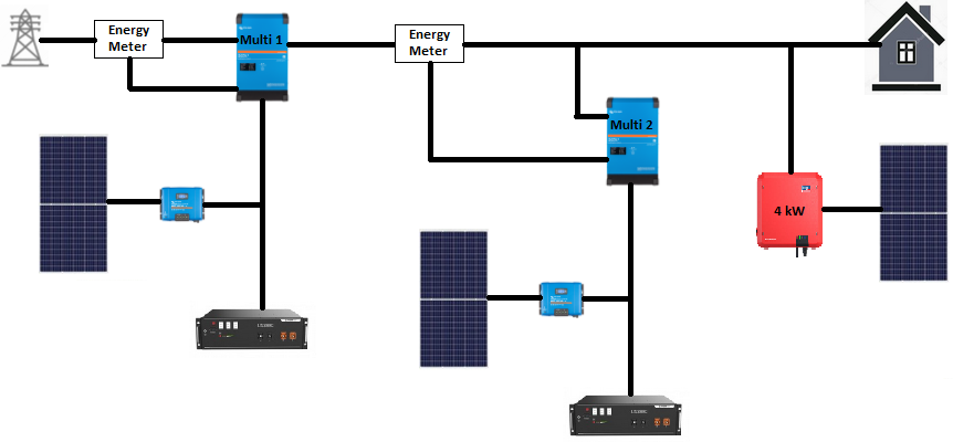
I am working on installing a Multiplus II 48/5000 at my home, where I already have an on-grid photovoltaic inverter SMA Sunny Boy 4kW and I have some questions I haven't found answers anywhere:

1. Is it possible to install two Multiplus II inverters in series (one of them connected to the other critical loads output) with non-shared batteries? How should I configure them? That would enable me to add a new Multiplus II in the future with another new battery on grid-parallel mode connected to first Multiplus II critical loads output.

1.1 If 1. question is possible, should I configure second one to not exporting to grid? Or first one could use frequency shifting (or similar) to control how much energy could export the second one?

1.2 Continuation of 1.1 question. Would be possible to have SMA Sunny Boy 4kW connected to the same critical loads output than second Multiplus II, having both controlled by frequency shifting? Or that is not possible as maximum power would exceed Multiplus II maximum power?

It appears a similar configuration could be done by using CerboGX large firmware, to be able to use Node-red to control some inputs:
- first Multiplus II critical loads frequency (could be updated depending on first Multiplus II is able to receive more power from critical loads or it cannot accept many more
- first Multiplus II AC In grid status (availabe/not available)
And to be able to control some things:
- second Multiplus II power exportation limit, being configure to 0 power exporattion into second Multiplus II if grid on first Multiplus II is disconnected

I've seen some other questions about similar solutions, but they were trying to control batteries load between two Multiplus II at the same time at the same battery load. I'm not interested on that. What I'm looking for is to:
1. If second Multiplus II (with AC In connected to first Multiplus II critical loads AC OUT) has batteries fully loaded, then it will share power with the other one if the other requires it; if the other doesn't require it and external grid is connected, power could be exported to grid; and if the other doesn't require it and external grid is disconnected, 0 power export should be configured into second Multiplus II
2. If first Multiplus II (connected to grid and with second Multiplus II connected to it's critical loads AC OUT) has batteries fully loaded, if second Multiplus II requires power, first Multiplus II can provide that power as if it were coming from real grid

Multiplus-IIVenus OSNode-REDmultiple inverters
victroninseries.png (107.4 KiB)
2 |3000

Up to 8 attachments (including images) can be used with a maximum of 190.8 MiB each and 286.6 MiB total.

3 Answers
anomalie avatar image
anomalie answered ·

Hi, I am interrested in similar system you described...
...and obviously it works!
https://www.victronenergy.com/blog/2018/03/13/victron-enhanced-off-grid-system/
Unfortunately no details or experience available. I have only excellent references to authors and mentioned Czech company.

By the way this australian guy https://www.youtube.com/watch?v=SsTkgoN6ENM explain method, how to configure Multiplus II and Phoenix inverter to share the load. I think, that this could be a start point, how to configure the system.

2 |3000

Up to 8 attachments (including images) can be used with a maximum of 190.8 MiB each and 286.6 MiB total.

Mariusz Zieliński avatar image
Mariusz Zieliński answered ·

Hello,

In my opinion this setup has more issues compared to alternatives:
- shared battery for parallel operation
- independent operation with independent internal AC networks

First of all your control loop is "quite loose". You will end up confusing inverters controllers (and cause them to shut down) and maxing out output on devices closer to the grid. If inside loop you involve system components which are prone to malfunctions (have no redundancy like node-RED on computer) it can happen that something will get stuck and in worst case lead to damage. Additionally I do not see real, practical advantages of such setup. Earlier stages will lose ability do deliver power much quicker than you expect and if you add fickle nature of solar sources you will get unexpected situations.

Your diagram is missing where you plan to put load and numbers (power capability of each unit and power use of load on each segment). Only situation I see it working semi-reliably but not efficiently is when each system sitting closer to the grid (the dominating one or one controlling behavior of the system) is way more powerful from next one (controlled one) and maybe carries lower load (extra devices consuming power from given segment). Of course no feeding power back. Failure (power loss) will start with first inverter circuit then second then third. Question is what real benefits come from feeding power from first stage to second versus separating and scaling up second stage or simply shutting down (via node-RED) less important load on single segment setup ?

Grid is treated as "infinite source of power" or energy lake and this is only reason inverter can "play with" it.

Inverter closer to the grid will always pump out as much as it can because it does not have way to detect where energy goes - to load or to following inverter. AFAIK there are no inverters capable of detecting surplus of energy on AC and feeding it upstream.

My advice is to parallel MultiPluses and get rid of SunnyBoy. Alternatively connect SunnyBoy independently and create separate AC circuit dedicated to critical devices. KISS rule. I subscribe to view where people who invest heavily in monitoring/observability often ignore usability of the system. They create contraptions that rarely are capable of working without human component in control loop.

I will reiterate importance of tight control loop concept. For that reason even in large setups you have on DC bus (one logical battery). For that reason you lock phase and power output of two inverters feeding to the same AC segment. Alternatives are problematic.

2 |3000

Up to 8 attachments (including images) can be used with a maximum of 190.8 MiB each and 286.6 MiB total.

rrroonn avatar image
rrroonn answered ·

I do not log in often, but thought I would belatedly share my personal experience.

From my experience, you can have a generator or another inverter feeding into the MP2 (I use MP2 48V/5000). To be successful, it is important that you do not have a grid code enabled on the final MP2 and you (a) enable the "Weak AC" and (b) "AC input current limit" to a sensible value to protect the source from overload.

If you have a grid code enabled, the MP2 will try to detect mains availability via frequency shifting - which the source generator or inverter might be extremely unhappy about.

2 |3000

Up to 8 attachments (including images) can be used with a maximum of 190.8 MiB each and 286.6 MiB total.