Idea

Jesse avatar image
Jesse suggested

1 wire Remote control of multiplus inverter using BMV relay output but no additional relay.

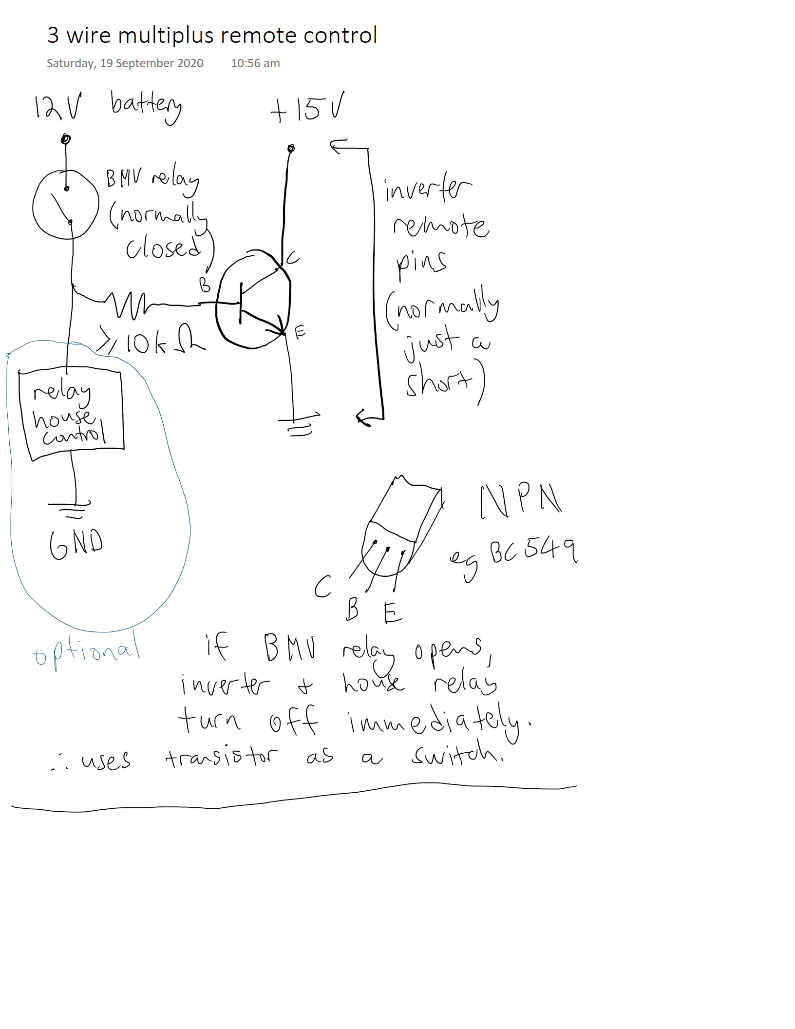
The standard readings suggest to use a relay to control the remote control pins of a multiplus or inverter. But relays are bulky, costly, prone to failure and use a measureable amount of power.

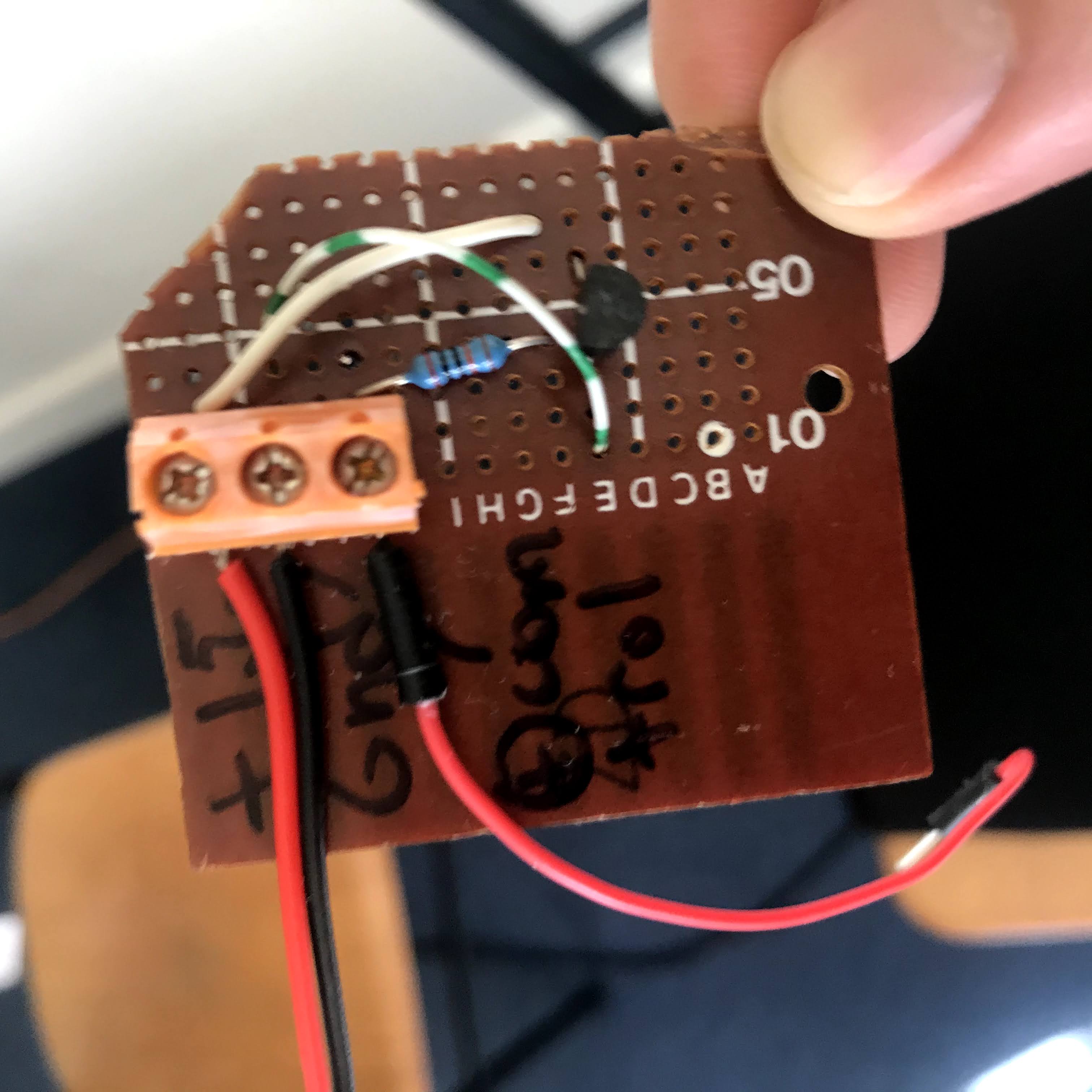
I put together a very simple circuit using only a resistor and a NPN transistor, which uses virtually no power, should be more reliable and possibly faster to respond to state changes. I've just soldered the components (badly) onto a small prototyping board. Make sure your copper is clean if you want a tidier result!

The only possible downside I've noted is that as the house (control) voltage dips below 12V it may not be adequate to keep the transister "closed" and the multiplus stopped inverting prematurely, but that has been hard to replicate in my system with a lithium battery since it is hard (and generally undesirable) to push the voltage lower than 12V anyway. Deep cycling lead acid systems might want to test this region in more detail, perhaps using a lower value resistor might help, though I've found anything lower than 10k to not work at all.

This device actually uses 3 wires, though 2 of them are just connecting to the remote terminals, and only 1 wire has to go to the input. High (>12V) equals on, low voltage will switch off. Higher house voltages should also work without modification but test carefully, I haven't. You'll need a multimeter to determine which of the multiplus or inverter's pins is positive and which is common ground - mine delivered a fraction of a milli amp when shorted and measured about 15V when open.

I haven't used a fuse, in theory it would be useless since the 100k resistor is unlikely to fail as a short, but something small like a 100mA quick blow fuse wouldn't hurt.

Any thoughts? Any dangers I haven't thought of?

MultiPlus Quattro Inverter ChargerPhoenix InverterRelay
2 |3000

Up to 8 attachments (including images) can be used with a maximum of 190.8 MiB each and 286.6 MiB total.

Jesse avatar image
Jesse commented

Wiring diagram, I suggest using higher than 10k value resistor, I'm using 100k, experimentation is required! Use a decent quality resistor ideally - carbon resistors are less reliable and can occasionally fail into a short (of so I've read).

2 |3000

Up to 8 attachments (including images) can be used with a maximum of 190.8 MiB each and 286.6 MiB total.

Jesse avatar image
Jesse commented

The (un)finished device - could be prettier, but it works.

2 |3000

Up to 8 attachments (including images) can be used with a maximum of 190.8 MiB each and 286.6 MiB total.

Vance Mitchell avatar image
Vance Mitchell commented

What inverter are you currently using?

From memory some smaller models only require a single wire connection to work, and the larger models can have a programmable input set as an emergency stop switch (i.e. shut inverter off)

1 comment
2 |3000

Up to 8 attachments (including images) can be used with a maximum of 190.8 MiB each and 286.6 MiB total.

Jesse avatar image Jesse commented ·

I have a 12/1600/70, one of the new models. Out of the box it has a jumper wire connecting the remote control terminals together to keep the device on. I haven't tried a direct connection between the +15V terminal and an external control voltage since that seems to be breaking the intended design, but that certainly would be simpler! Some careful experimentation required I think.

There's only one programmable input I think - by default used for a temperature probe but can be used to control charge current or disable cooling fan. Using it as a remote seems like duplicating an existing function?!

0 Likes 0 ·
vintdiesel avatar image
vintdiesel commented

Hi Jesse, a couple of notes here: Make sure that if fitting the house control relay, it has a flywheel diode connected across it, like a 1N4001 with the anode pointed towards ground, otherwise the inductive spike from the relay coil when the BMS contact opens, will zap the transistor with a kV or more!

Transistors are current driven devices, not voltage, so they do need some power. A more efficient device that is voltage driven and has a higher conductance would be an n-channel enhancement MOSFET for this application.

Sticking to using a transistor though, there should be:

A pulldown resistor to ensure the transistor reliably switches off when the BMS contact is open. I would suggest a 100k resistor from the transistor base lead, to ground.

The inputs of a Multiplus are actually analog/digital inputs, using a voltage above or below a threshold to resolve a 1 or a 0. I haven't found specs of what the input impedence of the inputs are, but on a 12V supply (which we should say goes nearer 15V when charging the battery) means that the impendence must not be less than 150 ohms or the 100mA collector to emmitter current rating of the transistor would be exceeded. I have no doubt that the input impendence would be significantly higher than that, but these things should be considered when using semiconductors.

Lastly the base drive current. This needs to be high enough to drive the transistor into saturation (using it as a switch), which will be calculated from whatever milliamps is being driven through the collector to emmitter divided by the transistor gain (BC549B >= 240). The maximum base resistor value has to be lower than the minimum supply voltage say 11 volts divided by the calculated base current. Also these small signal transistors have a maximum base current rating of around 5mA, so that same resistor must not be lower than say 15 volts divided by 5mA = 3k. All in all, the 10k resistor value is a pretty safe value to use.


1 comment
2 |3000

Up to 8 attachments (including images) can be used with a maximum of 190.8 MiB each and 286.6 MiB total.

Jesse avatar image Jesse commented ·

Thats some serious engineering advice, thanks! I will certainly try to incorporate into a version 2 device. Not sure I can process all of it but here's a few thoughts.

According to my measurements this transistor is only drawing microamps of power through its base, it's not a power device, for any power switching I agree a mosfet would be preferred, but here it seems adequate.

A pulldown resistor is redundant in my situation - it would be in parallel with the relay coil which has a much lower resistance - but without the relay this should probably be necessary. In testing surprisingly it didn't seem to make any difference.

As for the collector emitter current I haven't tested but when shorted with the default wire the remote pins of the inverter only passed I think around 0.1mA at most. My asumption has been that this wouldn't change when a wire was substitued with a transistor? Well under the 100mA limit of a small transistor. But safe design probably makes putting a few hundred ohm resister in series a good idea to avoid failure, assuming it doesn't confuse the inverter?

I need to spend some time getting my head around calculating base currents and gains, simple maths I know, but confusing. Awesome to see the maths behind my experimentation which found that anything much lower than 10k didn't work very well.

0 Likes 0 ·

Your Opinion Counts

Share your great idea, or help out by voting for other people's ideas.