question

Louis van der Walt avatar image
Louis van der Walt asked

Victron VenusOS driver for serial battery BMS - JBD / Daly / JKBMS / Renogy / ECS , etc.

Hi

I have created a VenusOS driver that can talk to BMS/Batteries that has serial communications (instead of the normal CANbus). RS485/RS232/TTL/UART and Venus 2.80+ have been tested.

Currently it works with

  • JBD BMS (LLT Power / Overkill Solar)
  • Daly BMS (Daly Smart BMS / Daly Sinowealth based BMS)
  • ANT BMS
  • MNB spi BMS - disabled by default as it requires extra libraries installed to work. Contact @Mike Dorsett for information
  • JKBMS / Heltec
  • Renogy
  • Tian Power BMS (Revov battery / LifePower)
  • ECS (GreenMeter)


The driver will act as Battery Monitor inside VenusOS which will also publish the battery to your VRM.
The following values are included:

  • State Of Charge
  • Voltage
  • Current
  • Power
  • Can handle batteries with from 3 - 32 cells
  • battery temperature
  • min/max cell voltages
  • raise alarms from the BMS
  • available capacity
  • history of charge cycles

The current release is on GitHub if you want to check it out.
You can up-vote for your BMS to be added to the driver in the here on github.
Documentation with install instructions and troubleshoot is available here


BMV Battery MonitorVenus OSBMSrs485
2 |3000

Up to 8 attachments (including images) can be used with a maximum of 190.8 MiB each and 286.6 MiB total.

126 Answers
bonzai avatar image
bonzai answered ·

Ok. fangen wir nochmals vorne an: kannst du mal deine komplette utils.py als txt hochladen? damit wir mal wissen welche Version du hast

Welches BMS hast du?

wie ist gerade der aktuelle SOC dazu?

Deine Batterie ist bereits bei 25 C. vieleicht greift auch bereits die Temperatur sicherheit?

Deine Batterie ist voll, vieleicht greift auch bereits der "Float" modus?

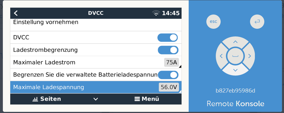
ist unter DVCC evtl. ein Limit eingestellt?

2 |3000

Up to 8 attachments (including images) can be used with a maximum of 190.8 MiB each and 286.6 MiB total.

Ulf Schneider avatar image
Ulf Schneider answered ·

Also das BMS ist ein JBD 1681474343485.png


Die Maximalströme sind großzügig richtig im BMS eingestellt:

Alle Spannungsschwellenverschachtelungen zwischen BMS und Multiplus habe ich als pdf Liste angehängt (spannungsschwellenendgültig).

Da ich nicht weiß, wie ich das Putty Fenster in Text wandeln kann, habe ich schnell Bildschirmschnappschüsse gemacht und auch angehängt (utils.py1-7).

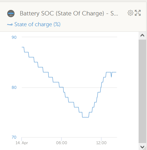
Heute morgen, wo die Venus GUI immer noch 60A Strombegrenzung für Laden und Entladen anzeigte, war der SOC um 72%. Dabei zeigt das Victron System geringfügig anders an, als das BMS, aber das ist erst einmal zweitrangig:

1681473538482.png

1681474966620.png

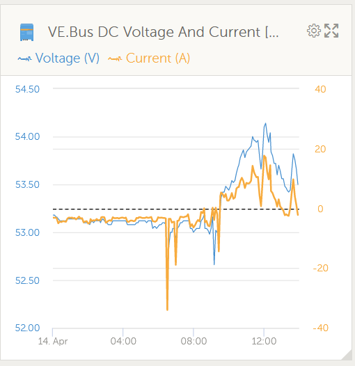
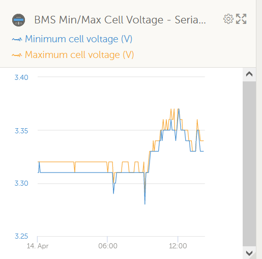
Hier die dazugehörige Batteriespannung und die Zellabweichung:

1681473625705.png

1681474819150.png

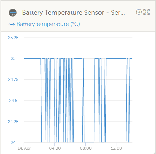
Hier der Temperaturverlauf (Dummerweis ist das der Mittelwert zwischen Fühler 1 und Fühler 2. Fühler 1 ist das BMS selbst (um 30° ) und fühler 2 und 3 sind die Batteriefühler (um 20°). Ich habe aber noch nicht herausbekommen, wie man die Temperarturfühler 2 und 3 als MittelwertLiFePoSpannungsschwellen.pdf zur Hauptanzeige im Venus und VRM bringt:

1681473938729.png


SpannungsschwellenEndgültig.pdf

utils.py1.jpgutils.py2.jpgutils.py3.jpgutils.py4.jpgutils.py5.jpgutils.py6.jpgutils.py7.jpg


1681473538482.png (20.9 KiB)
1681473625705.png (32.7 KiB)
1681473938729.png (29.0 KiB)
1681474343485.png (35.2 KiB)
1681474819150.png (28.4 KiB)
1681474966620.png (21.4 KiB)
utilspy1.jpg (76.8 KiB)
utilspy2.jpg (150.8 KiB)
utilspy3.jpg (120.9 KiB)
utilspy4.jpg (136.0 KiB)
utilspy5.jpg (108.0 KiB)
utilspy6.jpg (91.8 KiB)
utilspy7.jpg (87.8 KiB)
2 |3000

Up to 8 attachments (including images) can be used with a maximum of 190.8 MiB each and 286.6 MiB total.

Ulf Schneider avatar image
Ulf Schneider answered ·

1681476549092.png

Die Schwellen im DVCC sind auch passend eingestellt.


1681476549092.png (70.3 KiB)
2 |3000

Up to 8 attachments (including images) can be used with a maximum of 190.8 MiB each and 286.6 MiB total.

bonzai avatar image
bonzai answered ·

Also,

1. nimm in DVCC die Ladestrombegrenzung und die Batterieladespannung raus.

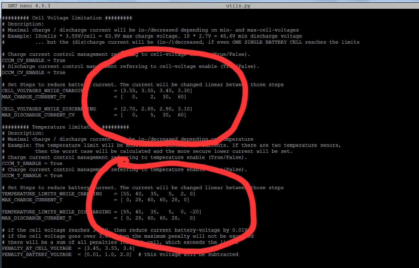
2. in utils.py Bild 2

du must natürlich die maxcharge current_cv und T sowie max discharge auch anheben :-). dort begrenzt du auf 60 Ampere

Dies ist noch die alte Version des Treibers. mit der neuen issu421 werden die kleinen Fehler behoben swie die Einstellungen vereinfacht. Ich hoffe das es bald die offizielle neu Version gibt :-). Bei der neuen Version änderst du wirklich nur noch diese Werte und der rest wird dann übernommen/berechnet. hier must du noch alles selber machen. Mr. Manuel hat hier echt einen tollen Job gemacht!


Du solltest die auch mal den linearen und step modus anschauen. für mich ist der Lineare viel besser da mein SOC wert nie richtig ist (JKBMS). Linar wird aus den Cellwerten berechnet.


2 |3000

Up to 8 attachments (including images) can be used with a maximum of 190.8 MiB each and 286.6 MiB total.

Ulf Schneider avatar image
Ulf Schneider answered ·

Danke,

Frage: kann man (wenn die neue Version ofiziell geworden ist) dann einfach mit

wget https//raw.githubusercontent.com/Louisvdw/dbus-serialbattery/master/etc/dbus-serialbattery/installrelease.sh

sh installrelease.sh

aktualisieren?

Falls ja, bleiben da die geänderten Settings aus der util.py erhalten?

Ich versuche heute Abend mal die benannten Änderungen auf der 2. Seite von utils.py und werde berichten.

Ich könnte das ja auch von hier machen (Firmenarbeitsplatz) über meine 5GHz Mikrotik Richtfunkstrecke nach hause, aber ich möchte vorsichtshalber beim reboot lieber in der Nähe vom Hardwaresystem sein, um eingreifen zu können, falls irgend etwas außer Ruder läuft.

Ulf


2 |3000

Up to 8 attachments (including images) can be used with a maximum of 190.8 MiB each and 286.6 MiB total.

bonzai avatar image
bonzai answered ·

Updaten kannst du dann so. Aber die utils ist neu und ganz anders aufgebaut! Dort gibt es dann die config.ini zum ändern, nicht mehr die utils! Da müssen Sie nicht mehr viel einstellen, nur noch auf Ihre persönlichen Bedürfnisse anpassen. Es zeigt dann in der Remote Console die einzelnen Batterien, farblich das Balancing, Alarme, Zustand usw. Eben viel mehr Spielereien

2 |3000

Up to 8 attachments (including images) can be used with a maximum of 190.8 MiB each and 286.6 MiB total.

bonzai avatar image
bonzai answered ·

Das musst du ändern. Die obere Zeile ist Volt und Die untere mit wieviel Ampere geladen werden darf. Und da steht bei dir max 60. Du kannst bei Bedarf die obere auch anpassen d.h immer bis: also bis 3.3 Volt mit 60A, dann bis 3.45 mit 30A usw.
52091-utilspy2.jpg


52091-utilspy2.jpg (279.4 KiB)
2 |3000

Up to 8 attachments (including images) can be used with a maximum of 190.8 MiB each and 286.6 MiB total.

Ulf Schneider avatar image
Ulf Schneider answered ·

Wunderbar, es funktiniert. Ich habe die Ladestromschwellen geändert in 0/2/35/70A, die Entladestromschwellen in 0/10/50/100A, und auch die temperaturabhängigen Stromschwellen adäquat angepasst. Dann mußte ich noch die maximale Zellspannung von 3,45V auf 3,47V erhöhen sowie die Float Spannung auf 3,5V (so wie es die Victron Systemparametrierung mit float- und bulkspannung will).

Auch die DVCC Begrenzungen stören nicht, wenn sie gleich oder weiter draußen liegen.

Jetzt aber meine Bedenken: Es sind jetzt 3 Systeme, die sich mit Komandos dazwischenfunken:

1.) Das BMS, mit Hardwaresicherheitsschwellen (Sicherheitsabschaltung internes Batterierelais) das stört nicht, die Strom und Spannungsschwellen liegen weit weg, das ist der letzte Notanker wenn alles versagt.

2.) Das BMS mit Software Handshake- Sicherheitsschwellen (Lade- oder Entladestromblockierung bei Überspannung, Unterspannung sowohl auf Zell- als auch auf Packebene), Übertemperatur und Untertemperatur. Die habe ich auch außerhalb der Schwellen im Multiplus und und ESS Assistenten gesetzt, die funktionieren aber (getestet, Venus zeigt die ergangenen Stopbefehle mit einer #xxx Nummer auf der GUI auch an) Das stört auch nicht.

3.) Das Multiplus System in Kombination mit dem ESS Assistenten.

Dort erfolgt eigentlich schon eine intelligente Lade/ Entladesteuerung , da sind auch Ladekennlinien (SOC und spannungsabhängig) hinterlegt, auch die Abschalteschwellen sind stromdynamisch (Dynamisches Abschalten).

4.) Jetzt weiß ich nicht, was der dbus-serialbattery Treiber eigentlich macht: Hat seine dynamische Steuerung Vorrang vor der dynamischen Steuerung im Victron System? Setzt er die Victron Steuerung völlig außer Kraft? Sind beide Systeme logisch worst case oder verknüpft?

Oder logisch ineinander verschachtelt (jeweils die sichereren Schwellen beider Systeme greifen zuerst)?

Ich tendiere dazu, nur einer von beiden dynamischen Steuerungen den Hut aufzusetzen, aber nicht beiden gleichzeitig.

Das könnte man doch zum Beispiel machen, indem man alle dynamischen Steuerungen in der util.py von = true auf = false setzt. Oder wird dann auch die dynamische Steuerung des Victron ESS Systemes ausgehebelt?

Die Sache ist doch viel tiefgründiger als gedacht und kostet sicher noch viel Gehirnschmalz ehe alles sinnvoll zusammenspielt.

Ulf

2 |3000

Up to 8 attachments (including images) can be used with a maximum of 190.8 MiB each and 286.6 MiB total.

Ulf Schneider avatar image
Ulf Schneider answered ·

Druckfehler : Natürlich die float Spannung auf 3,4V, nicht 3,5V !

2 |3000

Up to 8 attachments (including images) can be used with a maximum of 190.8 MiB each and 286.6 MiB total.

bonzai avatar image
bonzai answered ·

Das freut mich!

Ja der Treiber ist tiefgründig. Bei mir kommt erst der Treiber, minimal weiter der Multiplus und am Schluss das BMS. Das BMS bleibt der absolute Notanker!

Der Treiber ist genauer. Der Multiplus berechnet die Ströme nur. In der neusten Firmware 3.29 kann man unter DVCC einstellen wer steuern soll. Der Treiber steuert ja auch die MPPTs. Beobachte es, justiere es und du wirst sehen, es funktioniert und deine Freunde haben.

Aber du solltest dich etwas einlesen was der Treiber alles macht und kann. Daher empfehle ich dir auch die neue Version und evtl. den Linearen Lademodus. This goes sterben Steuerung dynamischer an, nicht so "hart" wie sterben Step-Funktion


2 |3000

Up to 8 attachments (including images) can be used with a maximum of 190.8 MiB each and 286.6 MiB total.

Ulf Schneider avatar image
Ulf Schneider answered ·

Ich habe die Victron Firmware auf die neueste 492 aktualisiert.

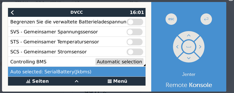
Unter DVCC finde ich aber keine Möglichkeit der Einstellung, wer steuern soll.

Wohl aber unter den ESS Einstellungen im Modus.

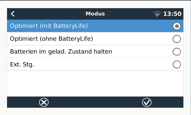
Ist der Button "Externe Steuerung" unter DVCC/ Modus die richtige Einstellung?

essexterne-steuerung.jpg


2 |3000

Up to 8 attachments (including images) can be used with a maximum of 190.8 MiB each and 286.6 MiB total.

Ulf Schneider avatar image
Ulf Schneider answered ·

Ich meinte natürlich die Einstellug unter ESS/ Modus/ Externe Steuerung. Unter DVCC habe ich keine ähnliche Einstellmöglichkeit gefunden.

2 |3000

Up to 8 attachments (including images) can be used with a maximum of 190.8 MiB each and 286.6 MiB total.

bonzai avatar image
bonzai answered ·

je nachdem was du willst. aber ich glaube extern ist falsch, ich habe optimiert ohne Battery life gewählt. Die DVCC einstellung erhältst du erst bei der VenusOS Firmware 3.00~4

1681740099710.png


1681740835152.png


1681740099710.png (47.5 KiB)
1681740835152.png (20.9 KiB)
2 |3000

Up to 8 attachments (including images) can be used with a maximum of 190.8 MiB each and 286.6 MiB total.

Ulf Schneider avatar image
Ulf Schneider answered ·

Alles klar, die Venus Firmware war gemeint, nicht die im Multiplus.

Nur leider kann ich nicht updaten, denn dann ist meine Displayhelligkeitssteuerung und Zeitabschaltung und sicher auch der dbus-serialbattery Treiber wieder weg?

Ich muß sicher neu aufsetzten?

Ich habe heute Nachmittag die lineare Strombegrenzun gewählt (nur von = False auf = True gesetzt).

Ergebnis: Sie funktioniert, aber es hat mir die Ladeschlußspannung bei dieser Einstellung heruntergsetzt (auf den Float Wert 54,4V) Trotz niedrigem SOC ! Ich habe aber nirgend wo anders ein Setting geändert. Woran kann das liegen ? Ich habe soeben wieder die Strombegrenzung auf grobe Schritte mit = False zurückgesetzt und die Ladeschlußspannungeinstellung wird wieder richtig mit 55,5V angezeigt.

Was kann man tun? Die lineare Stromtreppe mit ganz kleinen Schritten gefällt mir!

Ulf

2 |3000

Up to 8 attachments (including images) can be used with a maximum of 190.8 MiB each and 286.6 MiB total.

bonzai avatar image
bonzai answered ·

Der Treiber bleibt auch nach einem Update, muss höchstens neu gestartet werden mit sh restartservice.sh. Aber der Rest weiß ich leider nicht.

Genau das ist der Fehler in dieser Treiber Version! Darum habe ich Ihnen am Anfang den issue421 Treiber empfohlen. Dort ist genau dieser Fehler behoben worden. Leider wurde er bis heute noch nicht in die master Version übernommen. Ich denke Louisvdw hat momentan keine Zeit dafür. Aber Herr Manuel macht einen hervorragenden Job!!!!

2 |3000

Up to 8 attachments (including images) can be used with a maximum of 190.8 MiB each and 286.6 MiB total.

labtopia avatar image
labtopia answered ·

When is more Bluetooth capability to be implemented? I took a look and it doesn't seem much has been done to Bluetooth connectability. Specifically I am looking for ability to connect Overkill BMS w bluetooth to my Venusos on PI. Is this still something to be imprinted still and any idea when?

I am a +8 (for my 8 batteries i don't want to run wire to for serial) in support of this.

Thanks for the work on this!

Dave

2 |3000

Up to 8 attachments (including images) can be used with a maximum of 190.8 MiB each and 286.6 MiB total.

peregrines avatar image
peregrines answered ·

Hi!
I am using 4 battery banks with JK BMS and would love to switch to bluetooth because I get connection problems all the time via USB-TTL.
My only concern is if I can still use bluetooth to configure my BMS via JK BMS app?
Or will serialbattery bluetooth connection "occupy" my bluetooth exclusively?
Thank You!

3 comments
2 |3000

Up to 8 attachments (including images) can be used with a maximum of 190.8 MiB each and 286.6 MiB total.

dmsims avatar image dmsims commented ·
You will not be able to connect with the app
1 Like 1 ·
mr-manuel avatar image mr-manuel commented ·

Only one Bluetooth device can connect at once to the JKBMS. Normally you only need to make initial settings and then maybe some corrections, but it shouldn‘t be often that you change settings of the BMS. Anyway, if you connect Venus OS with the JKBMS you have to disconnect the BMS first in order to see it in the app. This can be done by rebooting the Venus OS or by executing

bluetoothctl disconnect MACADDRESS

via SSH.

1 Like 1 ·
peregrines avatar image peregrines mr-manuel commented ·
Thank You Mr-Manuel!
0 Likes 0 ·
B H avatar image
B H answered ·

Hi Louis, first of all thank you for your excellent work on this driver.

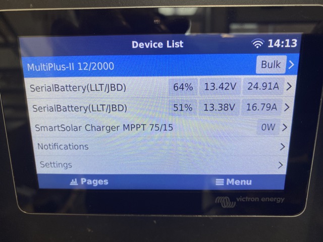
I have installed driver on Cerbo GX 3.01 Venus OS , having one Victron Multiplus 12/2000/80, Victron MPPT 71/15 and two 12V100ah JDB BMS's connected. Everything works great out off the box.!


img-2310-medium.jpeg


As i have tried to rename the bms names on the Gx device so i know wich one is physicaly connected but I noticed that the names go back to serial battery(LLT/JBD) :-(

Is it possible to change the name (with a variable) to set to product (device-product on gx) ? That is the "name" of the bms. That would be so much easier to see wich one to disconnect !

Thanks in advance !


2 comments
2 |3000

Up to 8 attachments (including images) can be used with a maximum of 190.8 MiB each and 286.6 MiB total.

derrick thomas avatar image derrick thomas commented ·
Did you install the latest nightly dev version?
0 Likes 0 ·
mr-manuel avatar image mr-manuel commented ·

The latest nightly from the dev branch has some issues with LLT/JBD. We are working on fixing that.

Please install this beta https://github.com/Louisvdw/dbus-serialbattery/releases/tag/v1.0.20230724beta


0 Likes 0 ·
B H avatar image
B H answered ·

nobody on changing the name for the battery in the gx screen ?

2 comments
2 |3000

Up to 8 attachments (including images) can be used with a maximum of 190.8 MiB each and 286.6 MiB total.

snoobler avatar image snoobler commented ·
I could go for that. I like making names that at least *I* find funny.
0 Likes 0 ·
pashka79 avatar image
pashka79 answered ·

Hi i want to try this driver with smart bt active balancer bms daly,heltec,jk will it work via Bluetooth ?


1 comment
2 |3000

Up to 8 attachments (including images) can be used with a maximum of 190.8 MiB each and 286.6 MiB total.

mr-manuel avatar image mr-manuel commented ·

Check the documentation and you will find out :)

https://louisvdw.github.io/dbus-serialbattery/general/supported-bms


0 Likes 0 ·
mr-manuel avatar image
mr-manuel answered ·

@Mike Dorsett could you help us with the documentation for installing a MNB BMS? https://github.com/Louisvdw/dbus-serialbattery/issues/590

2 comments
2 |3000

Up to 8 attachments (including images) can be used with a maximum of 190.8 MiB each and 286.6 MiB total.

Mike Dorsett avatar image Mike Dorsett commented ·
Sure, Though this was designed to work with the Maxim MAX 17852/3 chips using the SPI interface. I did go through the code recently to update it, but due to the difficulty in purchasing the PI3B+, and the fact that Victron forgot to include the SPI interface in the BBB-Venus image, this project (updating) got put on hold - until I find some time or some assistance in re-building the Venus code to enable the SPI port(s). Please let me know what hardware you have that you are trying to use for this?
0 Likes 0 ·
mr-manuel avatar image mr-manuel Mike Dorsett commented ·
Thanks for your fast reply. I have no such BMS, I only wanted to document it for other users. But if it‘s currently nearly impossible I will remove it for this time.
0 Likes 0 ·
pesi avatar image
pesi answered ·

Hi thanks for the good job of the developer!
I have a battery (LiTech Power) with BesTech BMS with Bluetooth interface inside. There is no wired interface available. Is there an existing or planed support for this?

2 |3000

Up to 8 attachments (including images) can be used with a maximum of 190.8 MiB each and 286.6 MiB total.

1984chris avatar image
1984chris answered ·

Hello

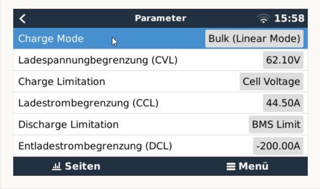
Is there a way to limit the discharge current(DCL) from e.g. a negative -200 A to a positive value 200A?Thanks.

LG Christoph


bms-parameter.jpg


bms-parameter.jpg (37.5 KiB)
1 comment
2 |3000

Up to 8 attachments (including images) can be used with a maximum of 190.8 MiB each and 286.6 MiB total.

mr-manuel avatar image mr-manuel commented ·
Please open an issue on GitHub.
0 Likes 0 ·
serveroutlet avatar image
serveroutlet answered ·

Hello,


I'm trying out this driver but I can only install stuff via the flash drive method because of an internet connection problem as this is in a remote install on the water.


So I downloaded the latest release available on github and installed it, it picked my up the JBD BMS and also my custom settings in the config.ini file.


Great, however, there is a big issue where the SOC reported is double the actual SOC or what the Xiaoxing and overkill solar app is reporting. Is there a downloadable fix for this? All other settings are working fine, but the incorrect SOC is a big issue.


A friend of mine is using the same cerbo, also with JBD but he can install via SSH however, the SSH install version does not support custom names or temperature names and other things as soon as you reboot it goes away, but it is reporting the correct SOC values.


3 comments
2 |3000

Up to 8 attachments (including images) can be used with a maximum of 190.8 MiB each and 286.6 MiB total.

elvis avatar image elvis commented ·

You need an entry in config.ini such as

CUSTOM_BATTERY_NAMES = /dev/ttyUSB3:JBD_BMS1

0 Likes 0 ·
dmsims avatar image dmsims elvis commented ·

Depends on the driver version:

"Driver version greater or equal to v1.0.20231128beta

  • The custom name is not saved to the config file anymore, but to the dbus service com.victronenergy.settings. You have to re-enter it once."

0 Likes 0 ·
mr-manuel avatar image mr-manuel commented ·

You can use the release from my repository to install via USB drive: https://github.com/mr-manuel/venus-os_dbus-serialbattery/releases/tag/v1.1.20240121

0 Likes 0 ·
Matt drummond bell avatar image
Matt drummond bell answered ·
Hi ! I have installed onto pi all running happy with battery aggregator ! What do I type into putty to invert the battery ?

I did read GitHub bits , I am not a programmer but have a little knowledge ! I just need to know exactly what to put in!

6x Daly bms

Many thanks matt


2 comments
2 |3000

Up to 8 attachments (including images) can be used with a maximum of 190.8 MiB each and 286.6 MiB total.

derrick thomas avatar image derrick thomas commented ·
I assume you mean to invert the current direction? Read the instructions on the GitHub for how to add configuration changes to the config.ini file. The setting you are looking for is can be found near the end of config.default.ini
0 Likes 0 ·
mr-manuel avatar image mr-manuel commented ·

There is a dedicated documentation page that includes a search: https://louisvdw.github.io/dbus-serialbattery/faq/#why-is-the-battery-current-inverted

0 Likes 0 ·
Matt drummond bell avatar image
Matt drummond bell answered ·

Hi I have so far setup 6x 12s 3.7v s using Daly bms s to a pi , monitoring 4x 48v 5000 multi plus, although just using 2 at mo as other two not needed at mo

150 mppt and grid inverters further down the line

I have changed voltage on defaults, inverted bms ,(-1)

I need to up the soc reset , and also alter the ccdm,dccm what are these settings based upon it’s says linear but I am wondering why the points are different from min max settings…

Max cell 4.2, min 3.2 float 3.8

I am curious about I control when I am down there next I will turn this on

This is a standalone system.

Keep up the good work !

If anyone can help with mods would be grateful!


2 |3000

Up to 8 attachments (including images) can be used with a maximum of 190.8 MiB each and 286.6 MiB total.

Related Resources