I am confused with the diagram shown in the distributor manual. Why there are 2 distributors in the Lynx system? One is not enough? If I remove the left one, does it affect the system?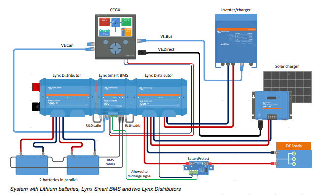
asked
LYNX SYSTEM CONFUSING
You can read more about it in the manual
Section for system design
I should have mentioned that. Thanks Alexandra.
Finally it's a question of design and system. There is no requirement for the Lynx Distributors at all, but they are making things so much easier and beside of visual fuse control you get that also from a GX device and VRM.
@Alexandra Hi, do you mean "If the Lynx System contains a Lynx Shunt VE.Can or Lynx Smart BMS, the batteries always have to be connected to the left side of the Lynx System and the rest of the DC system (loads and chargers) connect to the right side. This, so the battery state of charge can be correctly calculated."? Can I regard as that if I only use 1 Lynx Shunt or BMS with a distributor, then I can read the SOC?
I have read the manual, but I still didn't find the answer. And if I change the left distributor into power in, does it work?
The power in is where the batteries connect.
The distributor is where loads, mppts and charge sources are connected.
The shunt is always in the middle so it can count all the power in and out. You can orient it upside down to have it going right to left. There are stickers in the box to help with that.
For much smaller systems you can use the distributor only for all the connections (but then it is limited to 4 connections in and out). See the example. An you will need another way of having SOC calculated and fed to the GX.
As Stefanie mentioned it is a question of design. What are you looking for?
And I must admit that I don't understand the motivation replacing one Lynx Distributor into a Lynx Power In in such a expensive system (Lynx Smart BMS, SmartLithiums etc.) We are talking about a price gap of like 40 USD...
Hi @Chen Liang,
because the Lynx Smart BMS has a system side and a battery side separated by a contactor inside the BMS. With a Lynx Smart BMS it is not possible to remove one of the two Lynx Distributors.
Thank you Stefanie, but why another system use one Power in, Shunt and distributor, not a set of 2 distributors and a Shunt?
I don't know what other system you are referring to.
Look at the Lynx Smart BMS also as a Shunt with system side and battery side. The battery side has all battery minus wires connected.
If you don't want the Lynx Distributors, you can build your own bus bars. But the concept remains the same. Batteries must connect to the left side of the Lynx Smart BMS, Loads go to the right side. That cannot be changed or the Lynx Smart BMS will not work correctly.
The difference is the internal fusing.
I'm not 100% sure. There could be a potential problem with addressing (dip switches) the Lynx distributor on the right side.
In a system with Lynx Distributor left and right, the addressing starts on the left side, which gets address A and the one on the right side B. That is to make sure the fuse control in the Lynx Smart BMS can be correctly assigned. A Lynx Power In on the left side can break this concept.
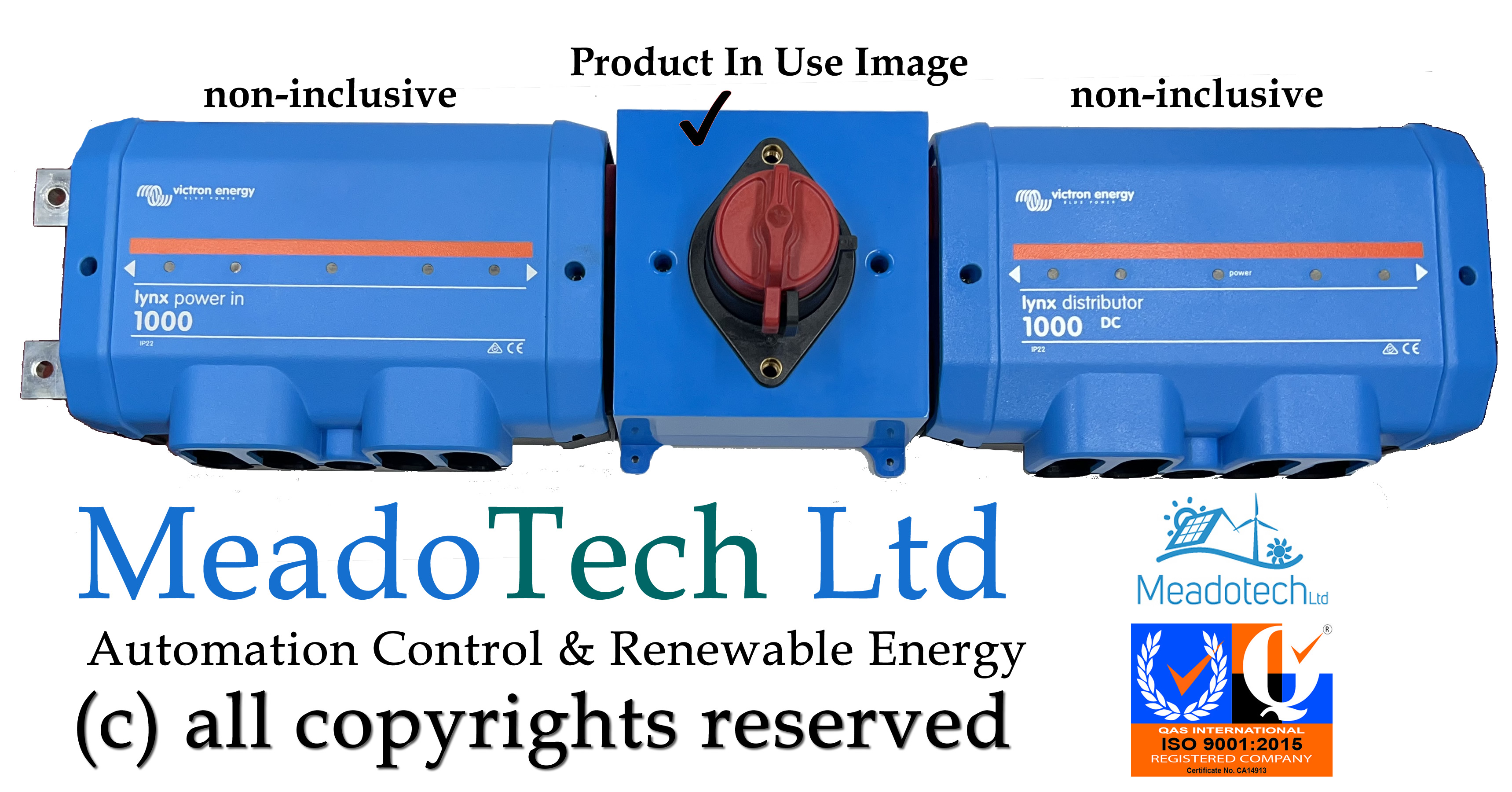
We have made enclosed 600A Battery Disconnect Switch to fit the Lynx DC Distribution systems M8, very helpful in Lynx installations.
MeadoTech Ltd United Kingdom