question

nebulight avatar image
nebulight asked

Multiplus Two Signal BMS Questions.

I have a multiplus 12/3000/120 and I'm looking to setup the two signal BMS assistant. I have three questions.

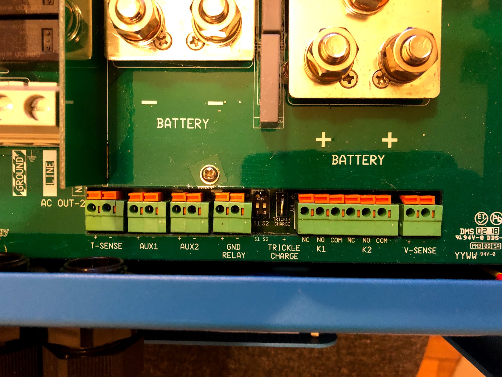
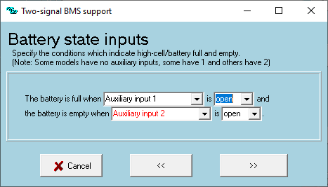
1. I've seen it mentioned that you have to use Aux1 and temp inputs, but when I load the assistant, I see you have the option to use Aux1 and Aux2 (though default is temp). Can I just Aux 2 and still use my temp sensor?

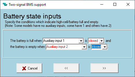
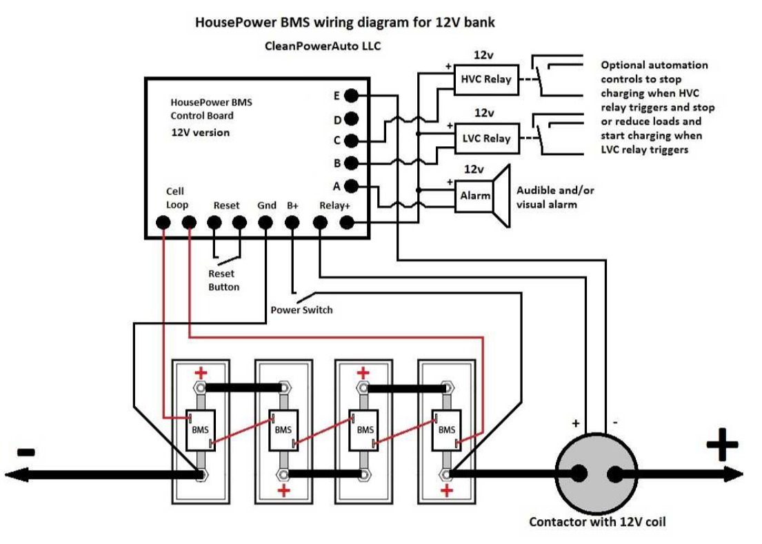
2. I have a Clean Power Auto MiniBMS 7 that has a main normally open contactor that will shut off the entire battery as well as two outputs that are designed for a normally closed relay. So I think I should be able to connect the BMS to the multi and configure it to be closed to turn off the charger (battery full) and turn off the inverter (battery empty). However I'm not sure about feeding 12v to the Multiplus as I've read in other threads it's not recommended. Any suggestions?

HVC turn on – 3.6V per cell
HVC turn off – 3.45V per cell
LVC turn on – 2.9V per cell
LVC turn off – 3.1V per cell

In addition to voltage hysteresis there is also 10 seconds time hysteresis for each threshold, to filter out brief voltage sags/spikes, which could be caused by engine starting or other brief heavy loads.

Cell level protection disconnects the bank if any cell is discharged to 2.6V to prevent battery damage.

Cell level protection disconnects the bank if any cell is overcharged to 3.65V to prevent battery damage.

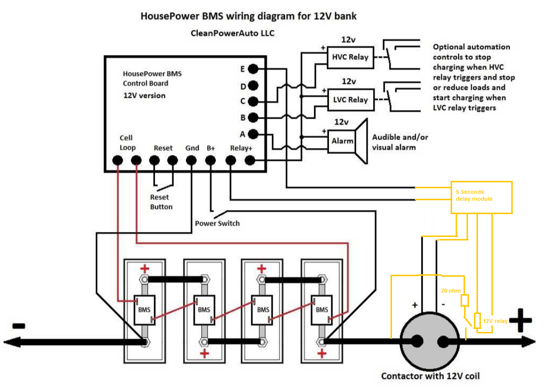
3. I've heard it's not wise run an inverter through a contactor (which is the main protection for the BMS) is not good. I'm not sure if the inrush current is bad for the contactor (possible welding issues) or the inverter. Would something like this work: http://www.rec-bms.com/datasheet/UserManualPrecharge.pdf and would anyone know if this could be used with other products other than the REC-BMS (not my BMS) since my BMS is switching on the negative? They come in 0.5, 1.5 and 4 second delay versions.

MultiPlus Quattro Inverter ChargerBMS
two-signal.png (7.5 KiB)
bms.png (303.1 KiB)
1554870121142.png (11.1 KiB)
2 |3000

Up to 8 attachments (including images) can be used with a maximum of 190.8 MiB each and 286.6 MiB total.

3 Answers
wkirby avatar image
wkirby answered ·

Hi there

1. MultiPlus does not have Aux2, so you need to use the Temp input. Those other options are there to cater for the other products which do have Ayx2, like a Quattro.

2. I presume that you mean it is not a good idea the feed 12V into the Aux / Temp inputs. You are correct, don't do this. Use dry relay contacts (potential free) or opto coupler. Your diagram suggests that you will be connecting dry relay contacts, so if you do that you will be fine.

3 Contactors are OK, I don't like them, but they are OK for emergency situations, not daily turning ON / OFF. It's in disconnecting that an arc may not be extinguished properly if the contactor is a low quality one. There is a decent amount of inrush current upon contactor closure, but again if this is a rare occurrence then it shouldn't be a problem.

There are solid state disconnecting products like the Battery Protect which can be driven externally in addition to being programmable for low Voltage events

1 comment
2 |3000

Up to 8 attachments (including images) can be used with a maximum of 190.8 MiB each and 286.6 MiB total.

federico993 avatar image federico993 commented ·

wkirby, Do you know if I can use BOTH CAN bus info from the BMS to Victron devices and BMS signals through Optocoupler with AUX and TEMP inputs to stop charging- stop discharging instructions?

Redundancy would be better if the CAN bus doesn't work.


Thanks!

0 Likes 0 ·
nebulight avatar image
nebulight answered ·

Thanks @wkirby As for the multi not having an Aux 2, I think the 2000va only has 1 aux, but I just cracked open my 3000 unit as it's not installed yet and it has an Aux 2:

And for using a secondary relay, I was considering inverting the signal with a NO NC relay so that I can use a battery protect to disconnect my charge sources and a second battery protect to disconnect my DC loads so you think I should be okay? What's the different between going through a relay and just getting the signal from the BMS board? I'm still somewhat new to all this.

And for the contactor I was told NOT to use a battery protect as current will flow both ways through mosfet. I upgraded to a multiplus just so I could have the two signal connection and not have to worry about disconnecting the inverter with a contactor. But like you said, only in emergency situations when the HVC and LVC conditons would fail to disconnect the loads/chargers. And it's a Tyco EV200 so it's a pretty decent contactor.

As for adding the pre charge relay, it shouldn't hurt anything right? I have a spare EV200 that I keep in the van, but I don't want to keep a spare multiplus ;)


multi.jpg (424.9 KiB)
2 comments
2 |3000

Up to 8 attachments (including images) can be used with a maximum of 190.8 MiB each and 286.6 MiB total.

wkirby avatar image wkirby ♦♦ commented ·

Ooops, sorry, my bad. You have the MultiPlus with the 50A transfer switch, which has an Aux2 (evidently). So, of course you can use that. The literature says to use temperature input for the MultiPlus because most of them don't have Aux2.
In your case, go ahead and use Aux2.

I like to use normally open contacts, In this configuration it's fail safe. Any wiring or BMS failure and the contacts will fail open. If a wire comes loose, then the circuit will go open. So, change your settings to "Battery is full when" AUX1 "is" - Open. Same for battery empty on Aux2.

Tyco are reputable, so you'll be fine with that. I'd still not recommend daily cycling of it unless you minimize loads before disconnecting.

Precharge can't hurt anything. Do what @MihaiR suggests. It seems it's a built in function of that BMS, so why no use it.

0 Likes 0 ·
nebulight avatar image nebulight wkirby ♦♦ commented ·

Thanks. As for the precharge, that's not the BMS I use, but that company makes the premade precharge box, so it's better than recreating the wheel ;)

0 Likes 0 ·
mihair avatar image
mihair answered ·

Hi @nebulight


Regarding question nb. 3, it is very easy to implement a delay start circuit depicted below:

The purpose of the circuit is to power the auxiliary relay at BMS startup and shunt the contactor with a low value resistor for charging the capacitors inside Multi. This circuit will power on the contactor after 5...10 seconds and at the same time will disconnect the resistor.

KR,

Mihai


2 |3000

Up to 8 attachments (including images) can be used with a maximum of 190.8 MiB each and 286.6 MiB total.