question

jaycobius avatar image
jaycobius asked

Connecting temperature sensor for SmartShunt with self-built LiFePo4 correctly (and two related questions)

Hi guys.

I am about to install the 500A/50mV-Shunt to my self-made battery (LiFePo4) system and bought the correct temp sensor for the connection with Vbatt+ and Aux.

As I have connected my cells main positive to a copper strip (20x3mm) in order to be able to use bigger lugs (the battery cells only have M6), and the heavy duty lug on the temp sensor has a M10 hole, I was wondering where I should ideally connect it:


9b99f6ca-6d04-4096-bffd-330d732bd37f.png


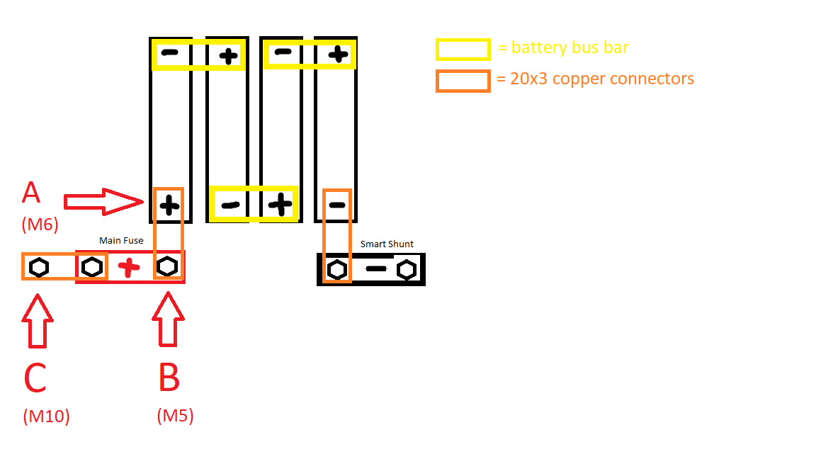
A, at the raw cells’ main positive

B, at the battery input of the main fuse, supplying it with power even when the fuse has blown.

C, at the fuse output, NOT supplying it with power, after the fuse has blown, but with a fitting M10 bolt. This is where I will connect the distribution bus bar with all my loads and chargers.


Also, I was wondering whether I could install a manual switch in the positive cable of the temp sensor, making it possible to turn off the shunt and prevent micro current in case I want to store the battery.

I have a Victron Smart Solar MPPT, BlueSmart IP65 and Orion-Tr in my setup. Am I understanding it correctly that the temperature sensor of the SmartShunt supplies all of these with the temperature reading when in the same network as the others, in order to optimize charging?

Thanks in advance for your answers!

Jacob

P.S.: Of course, I have a BMS between the battery main negative and the shunt, I just didn’t draw it in the above scribble, as the temp sensor should be connected to the positive side, as shown in the manual.

Lithium BatterySmartShuntbatteryTemperature Sensor
2 |3000

Up to 8 attachments (including images) can be used with a maximum of 190.8 MiB each and 286.6 MiB total.

1 Answer
Mike Dorsett avatar image
Mike Dorsett answered ·

https://www.victronenergy.com/upload/documents/SmartShunt/Manual_-_SmartShunt-en.pdf

The temperature sensor gets connected to the main Battery POSITIVE terminal, and directly to the shunt - no switch - as this also provides the power for the smart shunt. Manual section 3.4.3 page 7.

4 comments
2 |3000

Up to 8 attachments (including images) can be used with a maximum of 190.8 MiB each and 286.6 MiB total.

jaycobius avatar image jaycobius commented ·

Thanks, @miked. Love the Asterix icon! But all this information I was already aware of. As I built my battery on my own, I am simply not sure what exactly my main battery positive is in this setup. Which positive do you mean? A, B or C? They are all points on the positive side, but slightly closer or further away from the raw cell’s positive. I can see the point with the switch, too, but was wondering whether it is possible to disconnect the shunt when storing the battery with a small switch. Does the shunt keep the information stored when disconnected, or is it drawing a microcurrent to keep up the bluetooth


any ideas?

0 Likes 0 ·
seb71 avatar image seb71 jaycobius commented ·

Electrically, either point A, B or C are fine to use (the measured voltages should be nearly identical in all 3 points).

But since you also want to measure the battery temperature, you have to connect it at the battery terminal (point A). Otherwise it will measure the busbar temperature (in point B or in point C).

The SmartShunt positive wire has a inline fuse on it. Take out that fuse and the SmartShunt will be disconnected and not draw any power. But this should not be necessary unless you won't charge the battery for months or if you disconnected it while completely empty. The SmartShunt draws very little current.

If the SmartShunt is disconnected, it will lose the SOC status (it will be synchronized again after connecting it back and charging the battery). The settings will be kept.

0 Likes 0 ·
jaycobius avatar image jaycobius seb71 commented ·
Thanks a huge lot, Seb71. Sometimes it‘s so easy to get lost in details and completely forget why you wanted to do something in the first place. In my case: I indeed wanted to measure the temperature of the battery, to feed the data to the MPPT. Point A seems to be the correct answer then.


My only follow up question would be: can I take the heavy duty lug off the temp sensor, to replace it with a simple M6 ring terminal? The big boy is wayyyy too big for my M6 battery studs. It can‘t even be securely fastened by the corresponding M6 flange nut and spring washer, it just wobbles around, maybe losing connection when driving in rough terrain…

0 Likes 0 ·
jaycobius avatar image jaycobius jaycobius commented ·
Good point with the fuse, too!
0 Likes 0 ·

Related Resources

Additional resources still need to be added for this topic

Battery Compatibility

Did You Know - How to create a battery profile for non-Victron batteries?

Additional resources still need to be added for this topic

Victron temperature sensor disambiguation table - which product supports which sensor