question

5teve avatar image
5teve asked

Multiplus 12/3000/120-16 slow responding to DC loads - Voltage varying

HI All.

Not 100% sue that anything is wrong as such.. but haven noticed since turning my engel fridge off from mains (as its main priority and on an inverted socket) so it is on DC only, that the charge voltage is fairly unsteady in 'float' mode.

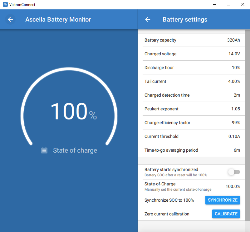
Set up is 326ah CALB celled (2p4s) battery - Daly Smart BMS - 250a Raspberry pi 3b+ running Venus OS 2.70~15 - BMV700 connected via victron VE Direct to USB cable, then the multiplus.

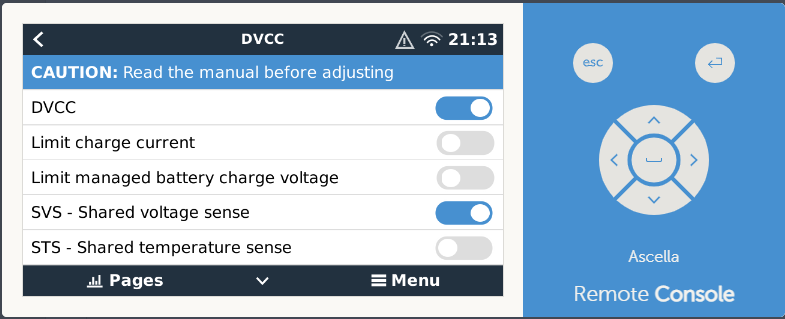
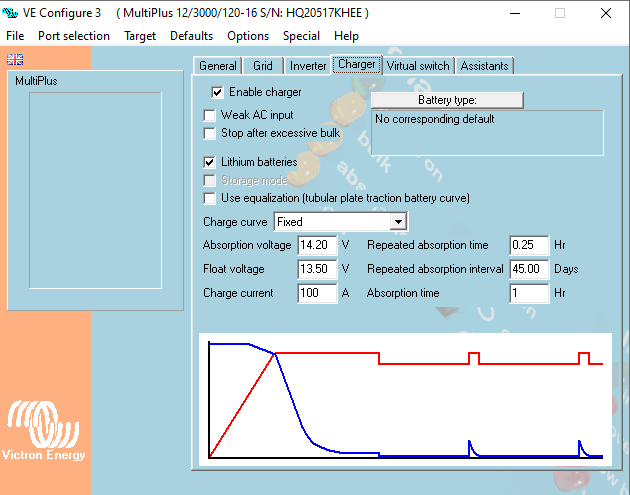
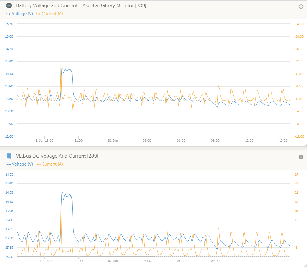
Set up is on shore power bulk to 14.2, absorption for as short as possible,. float at 13.5. DVCC Shared Voltage sense is ON

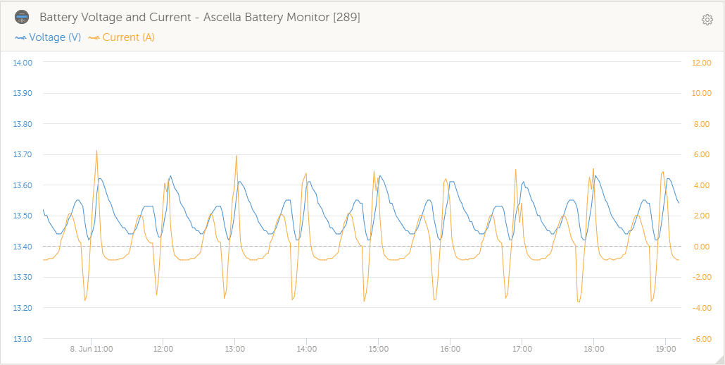
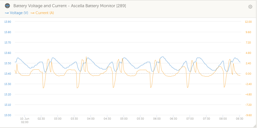
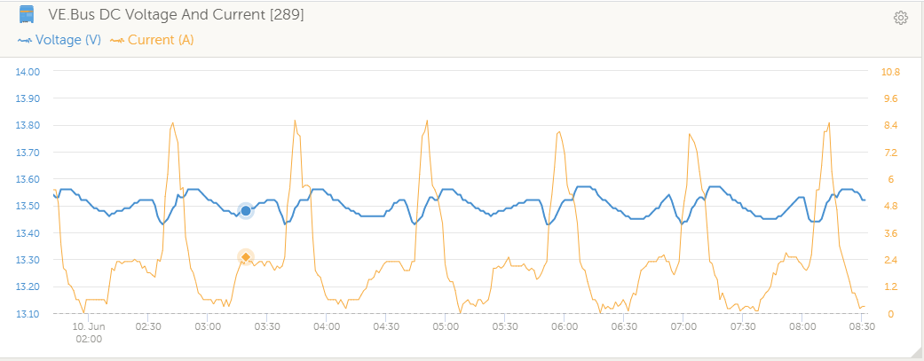
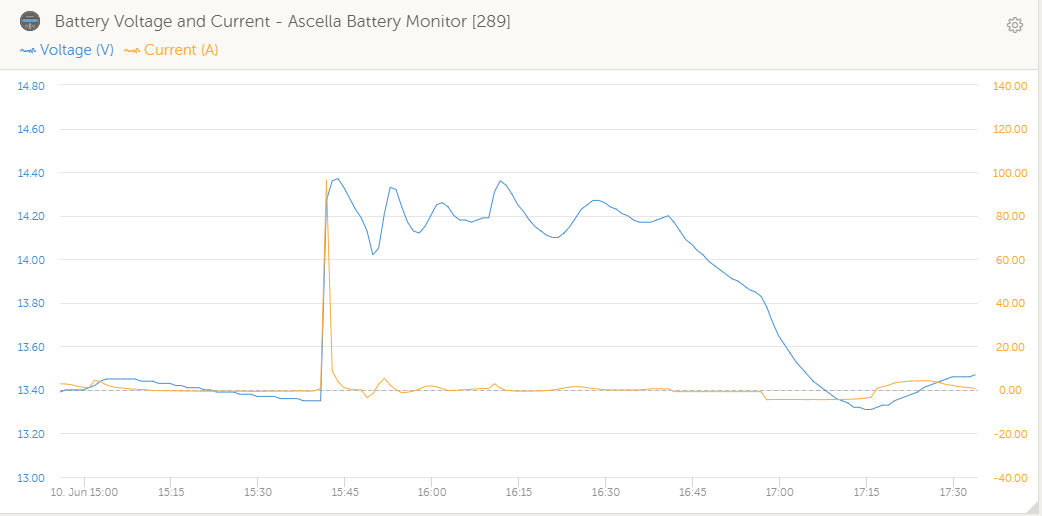
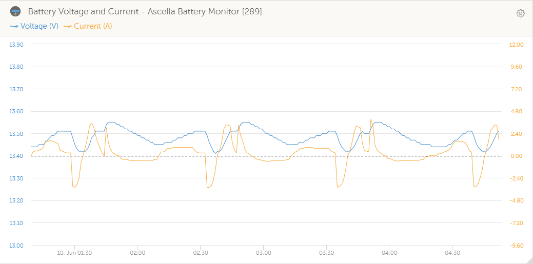
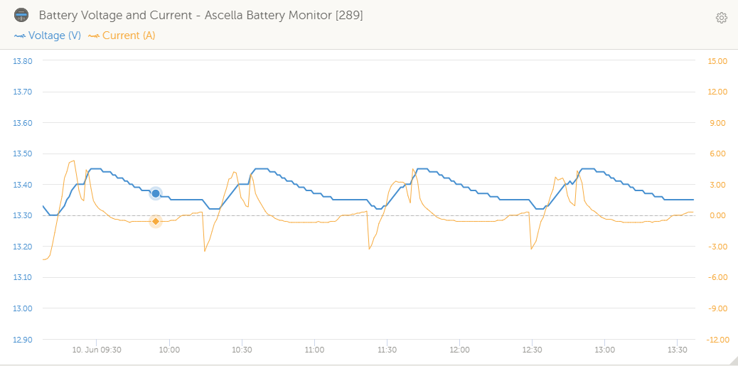
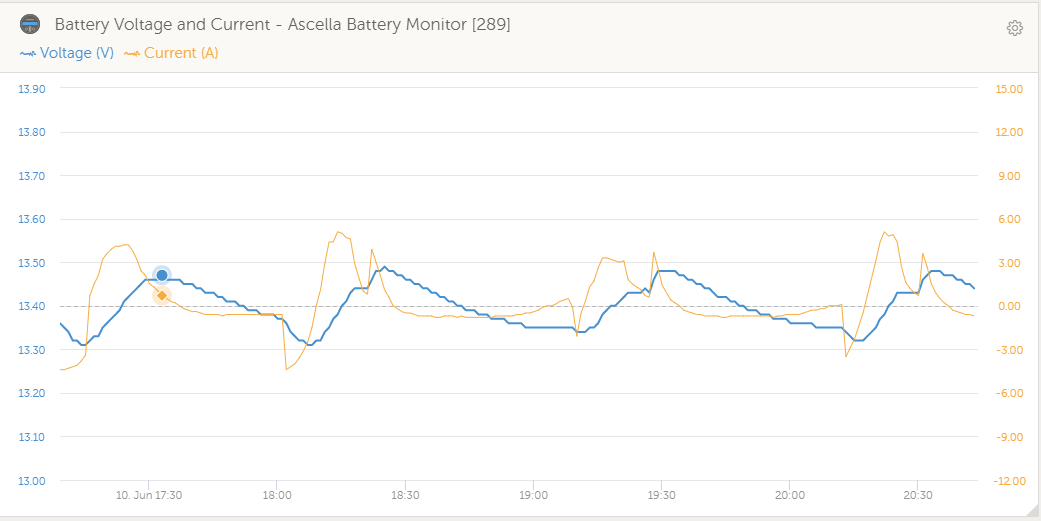
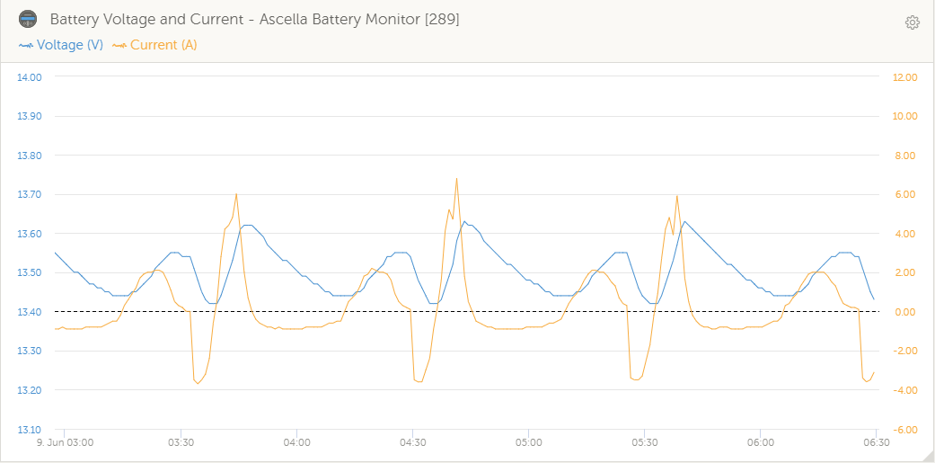
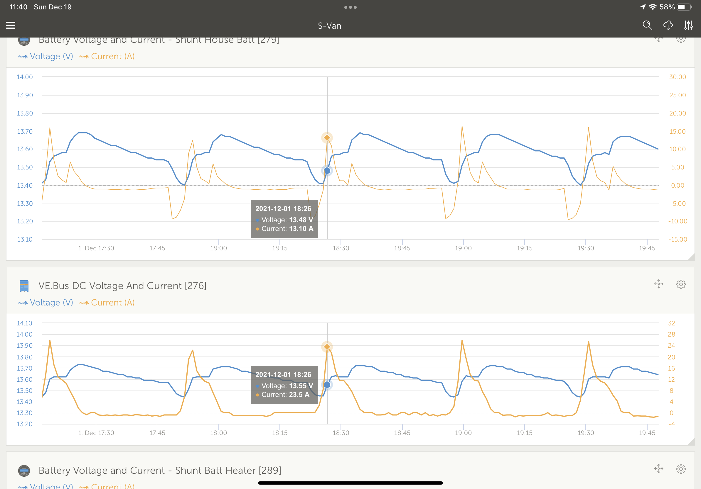
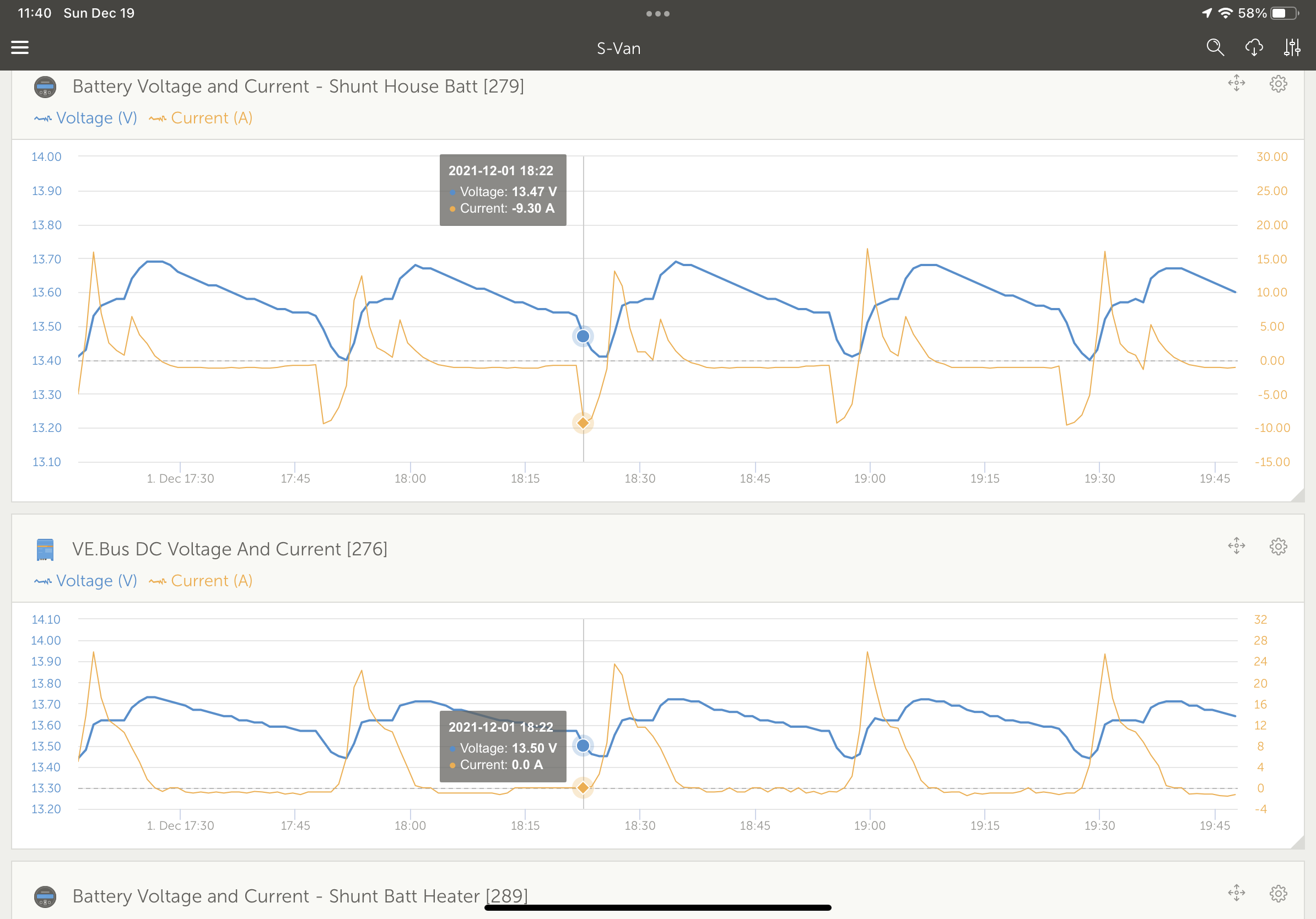
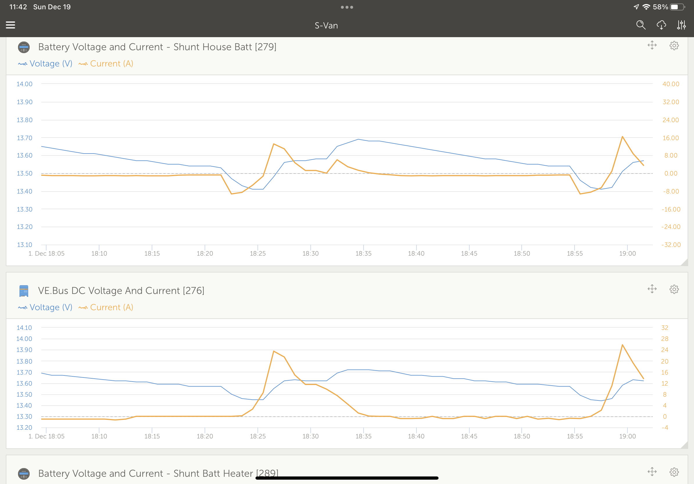
The thing I have noticed is that when the fridge kicks in, the voltage drops eventually 0.1v (over a few minutes) to 13.4v, the multiplus then wakes up and starts adding current, eventually overshooting 13.5v to 13.65, then dropping down slowly again.. and the process continues.

Prior to having the fridge on DC i had a steady draw of about 2.4amps, it took a while to settle but the charge voltage eventually settled at 13.5 and held...

I'm assuming that this is maybe by design... i just dont like the overshoot too much, am I missing a setting somewhere that tells the MP when to kick in (ie 0.1v below and stop 0.1v above?)


Steve


1623152190497.png

MultiPlus Quattro Inverter ChargervoltageDVCC
1623152190497.png (78.2 KiB)
1 comment
2 |3000

Up to 8 attachments (including images) can be used with a maximum of 190.8 MiB each and 286.6 MiB total.

klim8skeptic avatar image klim8skeptic ♦ commented ·

Set ur float voltage to 13,4v and see if the same things happen.

Multi's are not as programable as mppt's.

0 Likes 0 ·
5 Answers
JohnC avatar image
JohnC answered ·

Hi @5teve

This isn't by design, there's something wrong. The Multi can be seen to overshoot sometimes when correcting, but this takes seconds, not over the times shown in your screenpic. Too fast even for VRM to detect it usually, but can often be seen in VictronConnect with it's 'per-second' monitoring.

Maybe the bms, how you have it wired, whether under External Control, etc. I'm unfamiliar with that bms or indeed the rpi, but what you're seeing isn't normal.

Maybe supply more detail as to how you have it all setup and programmed, and someone here can surely set you right.


1 comment
2 |3000

Up to 8 attachments (including images) can be used with a maximum of 190.8 MiB each and 286.6 MiB total.

5teve avatar image 5teve commented ·

Thanks @JohnC

I'll try to provide more info.. but there isnt that much more I can think of..

  • Battery 326ah CALB Celled 2p4s battery connected to
  • Daly Smart 250a BMS (currently standalone, not part of the victron network) connected to
  • BMV 700 and shunt (Connected to Venus OS raspberry PI via VE direct to USB cable) Connected to
  • Victron Multiplus 12/3000/120-16 240V - Firmware 481 Connected via VE Bus to USB to
  • Raspberry PI 3b+ Running Venus OS 2.70~15 with a 5" touch screen.
  • All VE bus and VE direct adapters are Victron

DVCC shared voltage sense is ON so I understand the multiplus uses this instead of its own internal numbers

1623158029352.png

VE Configure - Multiplus Charge Settings -

1623157908681.png

BMV Settings -

1623158110370.png


If there is anything else that you need to see then please let me know and i'll post it..

Others have commented (on facebook group) theirs only varies by 0.05v hence me trying to work this out


Steve

0 Likes 0 ·
1623157908681.png (43.7 KiB)
1623158029352.png (42.4 KiB)
1623158110370.png (95.0 KiB)
JohnC avatar image
JohnC answered ·

@5teve

Thanks for that info. Can't see much wrong there. There's an alarm triangle showing on your DVCC pic - not related?

You say the Daly bms is standalone, no comms cables to any Victron kit?

I suspect the bms is the cause of this, allowing/disallowing current movement at it's own will. Where your BMV probe is located might be key to what you see, if it's located at the battery 'behind' the bms. So the Multi won't be actually reacting to the true voltage it's producing, rather the V supplied by DVCC. Maybe try disabling DVCC and record both V's to see what might be happening. Hope this makes sense..

This is indeed strange, and I'd love to hear how you go with it.

9 comments
2 |3000

Up to 8 attachments (including images) can be used with a maximum of 190.8 MiB each and 286.6 MiB total.

5teve avatar image 5teve commented ·

@JohnC no the alarm triangle was a grid loss from earlier in the day I didnt clear.. The jetty was having some electrical work being done.

Daly is standalone and connected directly to the battery at the battery.. the shunt is connected to the output of the BMS directly..

I cant see the BMS being the cause, as everything operates as it should (and very well I must add) apart from this oddity.. and it literally is just slow reactions to load.. As the BMS is 'smart' it has a serial connection (still waiting for a venus driver to be finished) and has bluetooth.. so I can see what is going on within the battery.. and nothing exeeds cell limits or anything so cannot see where it could cause an issue.. however I am far from an expert..

I think i have a few things to try.. first turn off DVCC and see how the multiplus acts.. secondly change the float voltage to 13.4v to see if that has any effect..

I'll update as I find things..


Steve

0 Likes 0 ·
JohnC avatar image JohnC ♦ 5teve commented ·

@5teve

The BMV shunt is located on the negative batt cable. The V it transmits comes from somewhere else. Where that is is what I'm suspicious of..

0 Likes 0 ·
5teve avatar image 5teve JohnC ♦ commented ·

@JohnC Sorry misunderstood you.. the +ve cable to the shunt is connected directly to the battery +ve terminal.. std cable supplied with shunt cut down to about 14" with 1a fuse in line.. nothing else so should be as pure as can be!

Steve

0 Likes 0 ·
JohnC avatar image JohnC ♦ 5teve commented ·

@5teve

Yeh, I think this is the issue. The Multi is trying to control to a V that's being influenced by the Daly. I'd either move the sensor or disable DVCC.

Might be interesting with DVCC off to see what that bms is doing with the batt V while the Multi holds it's own V constant. You should be able to monitor both V's.


0 Likes 0 ·
5teve avatar image 5teve JohnC ♦ commented ·

@JohnC could you elaborate on this a touch? How does the Daly influence the voltage? From what I understand, the BMS is there for protection and balancing. It has the ability to shut down on protection parameters, but for small currents and 'normal' voltages is just acts like it isnt there.. I can only monitor the Daly voltage if i'm on the boat, but when I was using a home made VE direct to USB cable and having issues (it wasnt isolated so gave the wrong voltage reading) once going to the victron cable I confirmed the BMV and BMS were showing the same voltage but i didnt monitor this over a period of time.

EDIT - Just to clarify, the BMS only passes the negative.. the +ve connections to each cell.. picture below..

With regard to moving the sensor do you meant the +ve for the shunt? If so where to? The +ve cable to the multi is no more than 1m long and is 120mm2 so there should be no voltage drop or anything along the way..

I have disabled DVCC for now, but even in the short space of time the graph is still profiling the same.. it just seems like 13.5v is a hard one for it to target quickly when there is an intermittent load. Once I have a few hours without DVCC i'll post the graph and then try reconfiguring for 13.4v float..

Steve


1623249687937.png

0 Likes 0 ·
1623249687937.png (2.2 MiB)
5teve avatar image 5teve 5teve commented ·

@JohnC this is DVCC disabled and multiplus managing its voltage..

Graph from Battery monitor

1623285234022.png


Graph from Multiplus

1623285268357.png


I've now reduced float to 13.4 and will post findings

Steve

0 Likes 0 ·
1623285234022.png (57.4 KiB)
1623285268357.png (55.2 KiB)
5teve avatar image 5teve 5teve commented ·

@JohnC and this is float at 13.4v.. certainly no better.. so I'll go with DVCC on and float at 13.4 and post the results.

1623310733164.png

0 Likes 0 ·
1623310733164.png (124.4 KiB)
JohnC avatar image JohnC ♦ 5teve commented ·

@5teve

Fascinating stuff - and I'm not onto it!

Can you relate some 'happening' in your system that might cause that recurring ~hourly cycle? The shunt is actually showing battery export, and this has me tossed. If it were wired in between the batts and bms that might explain it. But it shouldn't be there..

The small currents might be confusing me, and it's hard to follow the detail in the compressed vrm graphs without a pointer in hand..

Can anyone else shed light on this??

0 Likes 0 ·
5teve avatar image 5teve JohnC ♦ commented ·

@JohnC I appreciate your input.. :)

Yes as mentioned in the original post the hourly (I find it amusing that it is pretty much hourly) jump in current is the DC fridge kicking in for a few minutes.. its is this which is throwing the Charging voltage out.. for some reason the multiplus is kinda like..

oh we have a load.. i'll wait for the voltage to drop a bit then i'll over compensate.. until the voltage goes high.. oh but hang on, the loads gone.. bugger.. what do I do now.. oh i'll wait a bit for the voltage to drop again.. oh its gone too low again.. etc etc...

The graphs - One is the BMV (Ascella Battery monitor) the other is the VE bus. The BMV will be showing export as the multiplus is letting the battery drop when the load happens then as it realises the voltage is off target it overcompensates which is when you see the +4amps peak as it tries to catch up..

You have to admit its very consistent :) - I'm going to go back to 13.5v float with DVCC on.. as its no worse or better..

So now to try and understand why its got a +- 0.1v approx variation with loads.. it also overshoots when charging (something that has been mentioned a few times on facebook and on here) in the order of nearly 0.2v - Absorption starts at 14.2v.. you can see it hunting up and down and almost fading out..

1623329553951.png


Some zoomed in graphs.. from the BMV Sorry the scales are not identical in X or Y

13.5v DVCC off

1623329145319.png


13.4v Float - DVCC off

1623329215004.png


13.4v Float - DVCC on

1623329273975.png


13.5v Float - DVCC on

1623329323785.png

0 Likes 0 ·
1623329145319.png (47.6 KiB)
1623329215004.png (44.5 KiB)
1623329273975.png (44.0 KiB)
1623329323785.png (54.3 KiB)
1623329553951.png (44.5 KiB)
klim8skeptic avatar image
klim8skeptic answered ·

Post a photo of the exact location of the multi's voltage sense connection to your battery.

2 |3000

Up to 8 attachments (including images) can be used with a maximum of 190.8 MiB each and 286.6 MiB total.

5teve avatar image
5teve answered ·

So although we have added some details and done some testing, I seem to be getting nowhere with this slow responding charge / PSU...

Even if someone said thats normal and posted a graph of their equipment doing the same.. i'd be happy.. But from what I have determined... it looks to be abnormal...

Steve

2 |3000

Up to 8 attachments (including images) can be used with a maximum of 190.8 MiB each and 286.6 MiB total.

Steve avatar image
Steve answered ·

img-2975.pngimg-2974.pngimg-2976.png

Hi, I have the same behavior, a multiplus 12/3000 responding to a battery heater (almost resistive load)

Van connected to shore power, 400Ah Battleborn Lithium Batteries

In what mode is your multiplus, on or charger only?


img-2974.png (629.9 KiB)
img-2975.png (634.2 KiB)
img-2976.png (497.7 KiB)
2 |3000

Up to 8 attachments (including images) can be used with a maximum of 190.8 MiB each and 286.6 MiB total.