question

rolandchart avatar image
rolandchart asked

Fusing/Breaker confirmation and general system guidance

wiring-wanderbus.png

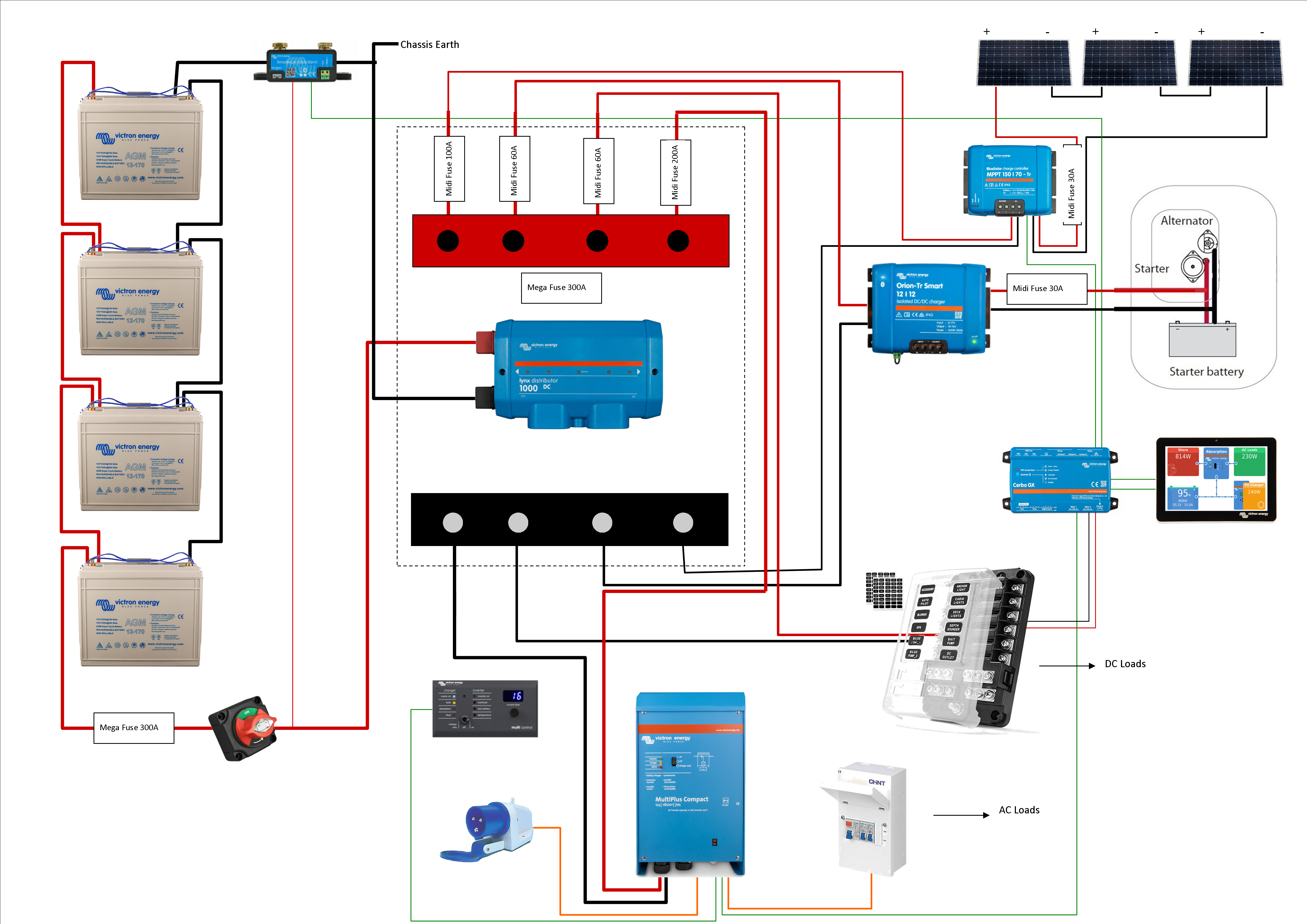
I've bought most of the stuff in this setup and now want to get fuses/breakers. But wanted to run it past those in the know before buying. Any comments on the above diagram would be welcome too; sizing of the wiring to follow when i've measured. Also does anyone have any recommendations on breakers/fuses?

MultiPlus Quattro Inverter Chargerfuseswiring diagram
2 |3000

Up to 8 attachments (including images) can be used with a maximum of 190.8 MiB each and 286.6 MiB total.

3 Answers
seb71 avatar image
seb71 answered ·

You choose the fuse based on wire cross section. The fuse protests the wire. It should blow before the current reaches the maximum current the wire can carry.


The positive wire for the SmartShunt should be connected to the battery terminal (and get the optional temperature sensor). This wire has its own fuse.


The wiring of those 4 batteries in parallel is sub-optimal. You should use busbars for batteries too and wire each battery to the busbar, with a fuse on each positive wire. The positive wires should be equal length. The negative wires should be equal length.


If you don't already have those lead-acid batteries, consider purchasing LiFePO4 instead. You can get half the capacity for similar or maybe even better performance.

2 |3000

Up to 8 attachments (including images) can be used with a maximum of 190.8 MiB each and 286.6 MiB total.

bodizzy avatar image
bodizzy answered ·

As far as I know, the Lynx only accepts Mega fuses, not Midi. What wire sizes are you using?


Also 2nd the comment about lithium if you're using anything power intensive like induction, MW, or other high wattage device -- look up Peukert's Law.

2 |3000

Up to 8 attachments (including images) can be used with a maximum of 190.8 MiB each and 286.6 MiB total.

Kevin Windrem avatar image
Kevin Windrem answered ·

I second seb71's recommendation to move the shunt to the battery positive terminal. That way it is always powered. Consumption is minimal and exceeds the typical zero current storage time of most batteries.

You might also want to move Cerbo to a direct battery connection with a separate disconnect switch so it can remain powered when other things are shut down. This would be important if you are opening the main battery disconnect switch to power down the system between trips. It might also be advantageous to have a separate disconnect for those loads you want to shut down when the system is in storage.

I would also wire the MPPT so it can charge the batteries when the "system DC" switch is off.

Bus bars for the battery connections is also a good idea. This is more important with lithium batteries due to their low internal resistance.

As boddizzy says, the fuses protect the wiring not the device. So the fuse needs to be located as close as possible to the source of maximum fault current. The only one that looks out of place is the one from the starter battery to the Orion DC-DC charger.

Cerbo provides AC input current limit and inverter mode control so the DMC is not really necessary.

2 |3000

Up to 8 attachments (including images) can be used with a maximum of 190.8 MiB each and 286.6 MiB total.