question

lucode avatar image
lucode asked

Home Assistant Modbus integration Tutorial

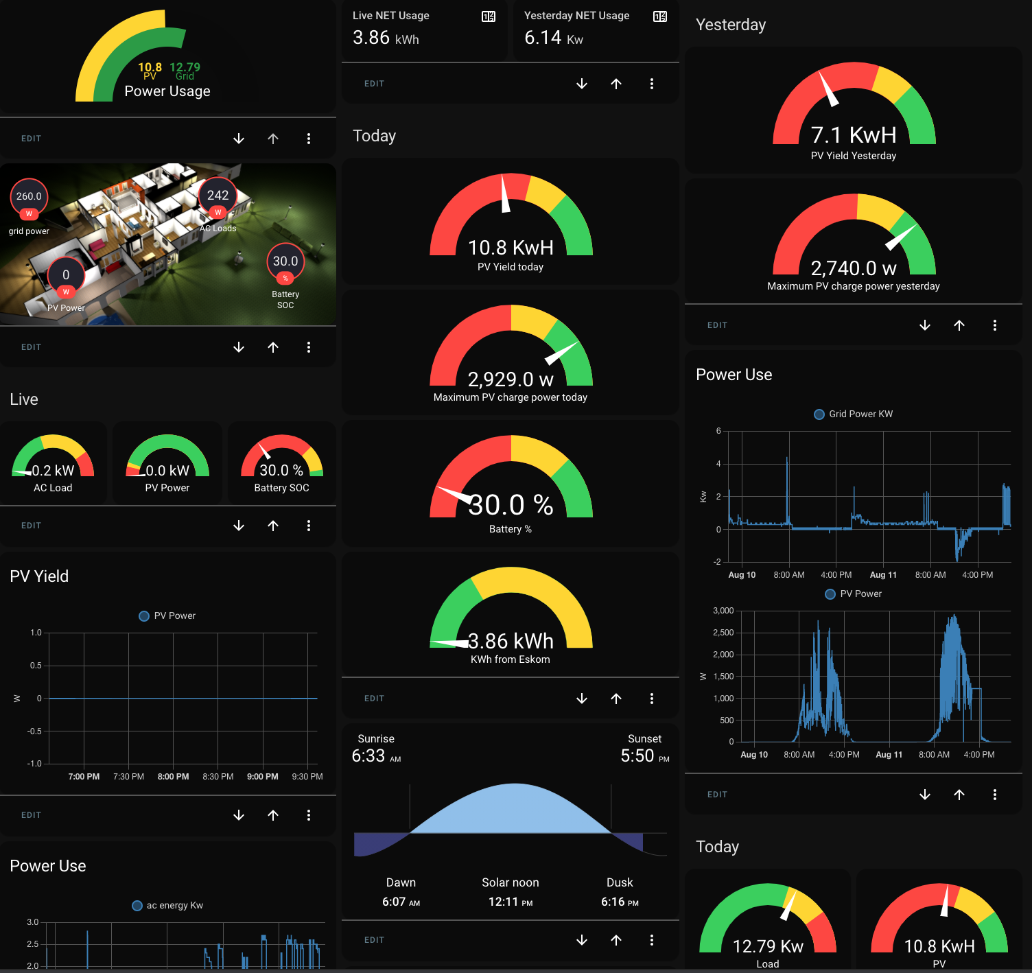
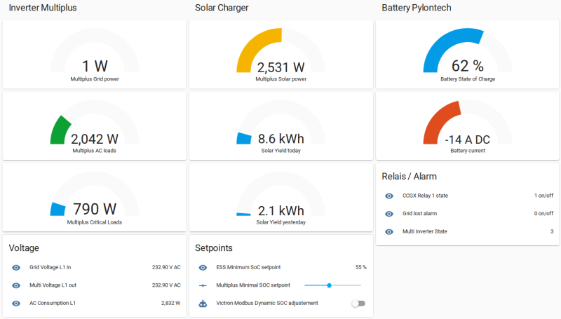
I did recently connected my EasySolar ESS to Home Assistant and the start was relatively straight forward. But to get all the stuff I wanted properly displayed, it did need quite some research for a Home Assistant newby. So I decided to let you know of my experience and eventually get some more tips, because I don't have finished everything what I have in my mind.

screenshot-victron-lovelace-20210223.png

Of course there are many ways (nicer ones too) to build the dashboard.


Step 1

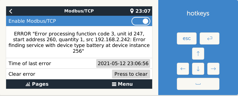
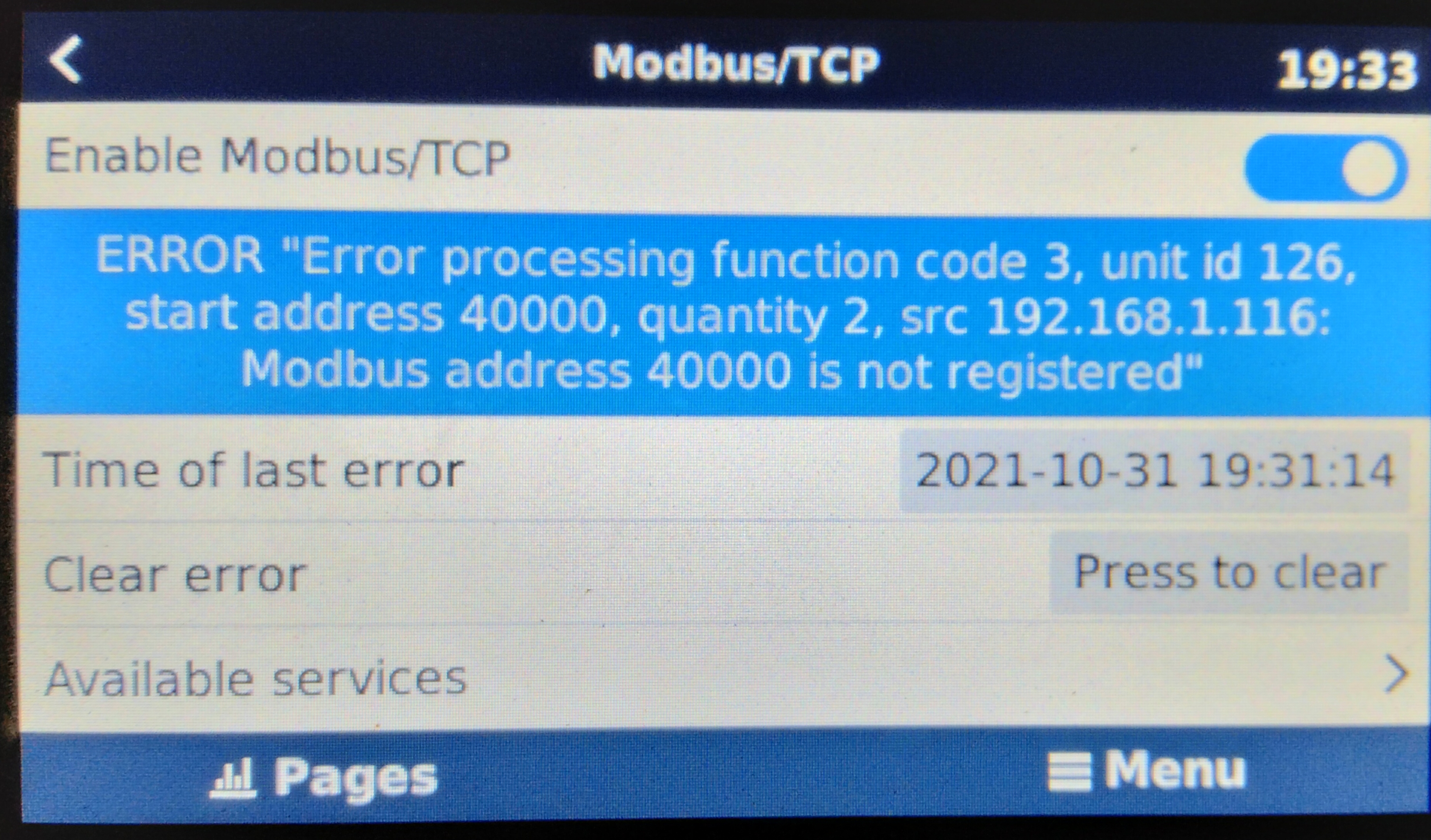
First you need to activate Modbus in the CGGX settings under 'Services'.
screenshot-victron-modbus-settings-20210223.png

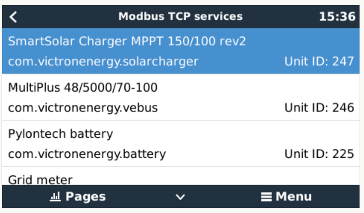
At this step it is helpful to write down your actual Unit ID's because they may differ from the one that I use.

Modbus TCPhome assistant
2 comments
2 |3000

Up to 8 attachments (including images) can be used with a maximum of 190.8 MiB each and 286.6 MiB total.

stepir avatar image stepir commented ·

Hi@lucode thanks a lot for your tutorial - it was a great starting point.


I have a ve.direct connected small charger (a phoenix smart) used for handling the starter battery of my motorhome. It has Unit ID: 247. I'd like to query it for reading the battery voltage and current and based on xls of registers list I think I should be using address 840/841. Here is what I configured as sensors:

      - name: "Camper Starter Volt"
        scan_interval: 60
        unit_of_measurement: "v"
        slave: 247
        address: 260

however pretty much any register I'm trying to read from this device the same error in the CCGX:


1620853654806.png


Do you know what I'm doing wrong? pretty much the rest works, and I'm able to read value both from my Quattro or my SmartSolar Charger.


Thanks!

0 Likes 0 ·
1620853654806.png (41.9 KiB)
ijeamaka-omayeka avatar image ijeamaka-omayeka stepir commented ·

Hi, have you been able to eliminate the reoccurrence of the error? If so, how was it done? I'm currently having an identical issue:

ERROR "Error processing function code 3, unit id 126, start address 40000, quantity 2, src 192.168.1.116: Modbus address 40000 is not registered"

img-20211102-054809.jpg


0 Likes 0 ·
17 Answers
lucode avatar image
lucode answered ·

Step 2

Next you need to activate the Modbus communication to HA (Home Assistant). I did create this file with the name modbus.yaml and integrated it into the configuration.yaml.

# cat modbus.yaml
# configuration entry for a TCP connection
# modbus:
name: victron
type: tcphost: <CGGX IP address>
port: 502

After this you need to create, if not there, a file with the name sensors.yaml and integrate it into the configuration.yaml too.

The content of my sensors.yaml file looks as this one. Scan interval is set to 10 sec.

# Victron device over Modbus: system entries
- platform: modbus
  scan_interval: 10
  registers:
# Victron device over Modbus: system 
    - name: 'CCGX Relay 1 state'
      hub: victron
      unit_of_measurement: "on/off"
      slave: 100
      register: 806  
    - name: 'AC Consumption L1'
      hub: victron
      unit_of_measurement: "W"
      slave: 100
      register: 817
      
    - name: 'Multiplus Grid power'
      hub: victron
      unit_of_measurement: "W"
      slave: 100
      register: 820
    - name: 'Multiplus Solar power'
      hub: victron
      unit_of_measurement: "W"
      slave: 100
      register: 850
      
    - name: 'ESS Minimum SoC setpoint'
      hub: victron
      unit_of_measurement: "%"
      data_type: uint
      slave: 100
      register: 2901
      scale: 0.1
      
    - name: 'Maximum System Grid Feed In'
      hub: victron
      unit_of_measurement: "W"
      data_type: int
      slave: 100
      register: 2700
      # command_on: 4000
      # command_off: 40
      # verify_state: false

# Victron device over Modbus: Pylontch Battery 
    - name: 'Battery current'
      hub: victron
      unit_of_measurement: "A DC"
      slave: 225
      register: 261
      register_type: input  
      scale: 0.1
      precision: 0

    - name: 'Battery State of Charge'
      hub: victron
      unit_of_measurement: "%"
      slave: 225
      register: 266
      register_type: input  
      scale: 0.1
      precision: 0
      
# Victron device over Modbus: vebus
    - name: 'Multiplus Critical Loads'
      hub: victron
      unit_of_measurement: "W"
      slave: 246
      register: 23
      register_type: input  
      scale: 10.0
      precision: 0  
      
    - name: 'Grid Voltage L1 in'
      hub: victron
      unit_of_measurement: "V AC"
      slave: 246
      register: 3
      register_type: input  
      scale: 0.1
      offset: 0
      precision: 2
    - name: 'Multi Voltage L1 out'
      hub: victron
      unit_of_measurement: "V AC"
      slave: 246
      register: 15      
      scale: 0.1
      offset: 0
      precision: 2 
    - name: 'Grid lost alarm'
      hub: victron
      unit_of_measurement: "on/off"
      slave: 246
      register: 64        
    - name: "Multi Inverter State"
      hub: victron
      slave: 246
      register: 31
      # Inverter States, 0=Off;1=Low Power;2=Fault;3=Bulk;4=Absorption;5=Float;6=Storage;7=Equalize;8=Passthru;9=Inverting;10=Power assist;11=Power supply;252=Bulk protection   
      #  com.victronenergy.solarcharger slave: 247
    - name: 'Solar Yield today'
      hub: victron
      unit_of_measurement: "kWh"
      slave: 247
      register: 784
      data_type: uint
      scale: 0.1
      precision: 1 
    - name: 'Solar Yield yesterday'
      hub: victron
      unit_of_measurement: "kWh"
      slave: 247
      register: 786
      data_type: uint 
      scale: 0.1
      precision: 1
      
# Templates Modbus calc
- platform: template
  sensors:
    multiplus_ac_loads:
      friendly_name: 'Multiplus AC loads'
      value_template: "{
                  { states('sensor.ac_consumption_l1') | int - states('sensor.multiplus_critical_loads') | int }}"
      unit_of_measurement: "W"
      
    multiplus_minimal_soc_set_setpoint:
      friendly_name: 'Multiplus Minimal SOC setpoint scaled'
      value_template: "{
                  { states('input_number.multiplus_minimal_soc_setpoint') | int * 10 | int }}"
      unit_of_measurement: "%"

Please note that you need to adapt the sensors to you installation. Eventually the slave: number may differ too.
At the end you find two templates one is for calculating the AC loads (non critical), the second one I need to a write a value (ESS min. SOC) from HA to the CGGX. It just corrects to scale factor for the value to write.

1 comment
2 |3000

Up to 8 attachments (including images) can be used with a maximum of 190.8 MiB each and 286.6 MiB total.

lucode avatar image lucode commented ·
This settings are not anymore running with HA since version 2021.5. See new example at the bottom.
0 Likes 0 ·
lucode avatar image
lucode answered ·

Step 3 (Writing a value)

The automation to write a value would look as this example (min. SOC ).

# from automations.yaml
- id: '1614077768708'
  alias: Victron Modbus Write min SOC manual
  description: ''
  trigger:
  - platform: state
    entity_id: input_number.multiplus_minimal_soc_setpoint
  condition: []
  action:
  - service: modbus.write_register
    data:
      hub: victron
      unit: 100
      address: 2901
      value: '{
                  { states.sensor.multiplus_minimal_soc_set_setpoint.state|int }}'
  mode: sing

Please note, that you need to create a slider first in Configuration->Helpers. Mine has the name multiplus_minimal_soc_setpoint, this value is the trigger of the automation to write the new value to the CGGX.

1 comment
2 |3000

Up to 8 attachments (including images) can be used with a maximum of 190.8 MiB each and 286.6 MiB total.

stepir avatar image stepir commented ·

thanks - very helpful


mode: sing 

should be

mode: single


I'm trying to use your example to set Active input current limit - in my case the value is read here:

      - name: "Camper current Limit"
        scan_interval: 60
        unit_of_measurement: "A"
        slave: 246
        address: 22
        scale: 0.1
        precision: 1
        device_class: current
        input_type: input

I've defined an helper with the name input_number.camper_current_limiter and my automation is

- id: '1620734902145'
  alias: 'camper: set max current on charger based on input select'
  description: ''
  trigger:
  - entity_id: input_number.camper_current_limiter
    platform: state
  condition: []
  action:
  - service: modbus.write_register
    data:
      hub: victron
      unit: 246
      address: 22
      value: '{
                  { states.sensor.camper_current_limiter.state|int }}'
  mode: single

however when I try to run it I can trace this error:

Triggered by the state of input_number.camper_current_limiter at May 13, 2021, 10:10:04 AM

Call service modbus.write_register


Stopped because an error was encountered at May 13, 2021, 10:10:04 AM (runtime: 0.00 seconds)expected int @ data['value'][0]

seems like the input helper is not providing an integer?

0 Likes 0 ·
lucode avatar image
lucode answered ·

Step 4

The last step is adding the dashboard If you are interested about the code of mine (see at the top), here a pastebin of the code https://pastebin.com/R1Eaz5zt.

Next step is to automate the "ESS Min SOC" value according weather forecast and State of Chart from last days.

1 comment
2 |3000

Up to 8 attachments (including images) can be used with a maximum of 190.8 MiB each and 286.6 MiB total.

lucode avatar image lucode commented ·

The setup in pastebin is already outdated, see https://github.com/lucode/home-assistant where you can find all the updated information.

0 Likes 0 ·
wkirby avatar image
wkirby answered ·

Thank you very much for taking the time to share this.
I have Home Assistant running as a VMware VM, but that's as far as I got. I will most likely find this information useful.

2 |3000

Up to 8 attachments (including images) can be used with a maximum of 190.8 MiB each and 286.6 MiB total.

palom170 avatar image
palom170 answered ·

Thank you so much for sharing your knowledge, I am trying to control the feed into grid, but I have not got yet, could you help me? Thanks in advance

2 |3000

Up to 8 attachments (including images) can be used with a maximum of 190.8 MiB each and 286.6 MiB total.

butter-fry avatar image
butter-fry answered ·

I was poking around the forum here looking for answers for something else.. I'll contribute too.


To add information about what the charger is doing (Charger State Register 775) we just need to create a Template Sensor in HA like so:

  - platform: template
    sensors:
      charger:
        friendly_name: "Charger State"
        value_template: >-
          {% if is_state('sensor.bsc', '0') %}
            Off
          {% elif is_state('sensor.bsc', '3') %}
            Bulk
          {% elif is_state('sensor.bsc', '2') %}
            Fault 
          {% elif is_state('sensor.bsc', '4') %}
            Absorbtion
          {% elif is_state('sensor.bsc', '5') %}
            Float
          {% elif is_state('sensor.bsc', '6') %}
            Storage
          {% elif is_state('sensor.bsc', '7') %}
            Equalize
          {% elif is_state('sensor.bsc', '11') %}
            Other (Hub-1)
          {% elif is_state('sensor.bsc', '252') %}
            External Control   
          {% else %}
            N/A
          {% endif %}

and then pull in the 775 register under your modbus platform

    - name: bsc
      hub: victronsolar
      slave: 239
      data_type: uint
      register: 775            

The output looks like this when added to a normal Entities Card on the frontend :

1616532313606.png

1616532397071.png

This could also be modified to do any of the text style registers such as On/Off of what @lucode posted with the Relay state (register 806 or register 64)


1616532313606.png (2.8 KiB)
1616532397071.png (19.6 KiB)
2 |3000

Up to 8 attachments (including images) can be used with a maximum of 190.8 MiB each and 286.6 MiB total.

stepir avatar image
stepir answered ·

I have also another question for @butter_fry and@lucode who've been successful in configuring ha modbus/victron:


The official modbus documentation here Configuring platform sensor talk about configuring modbus and its sensor in configuration.yaml - in this way I have my sensors recognised. However if I follow @lucode direction in its step (using modbus.yaml and sensor.yaml) I don't have any error in HA logs but no sensors are being created?


anyone else reporting success/failure?


1 comment
2 |3000

Up to 8 attachments (including images) can be used with a maximum of 190.8 MiB each and 286.6 MiB total.

lucode avatar image lucode commented ·

You need to include those files in configuration.yaml

# Templates / modbus conf
modbus: !include modbus.yaml
# Includes all Templates / Sensors in folder sensor
sensor: !include_dir_merge_list sensor/
binary_sensor: !include binary_sensor.yaml


0 Likes 0 ·
fjordaan avatar image
fjordaan answered ·

have been using my modbus setup for around 2 years, there was a change in the configuration of the yaml file, make sure you are using the correct format:

new format:

- name: "Grid Power KW"

slave: 100

address: 820

unit_of_measurement: "kW"

scale: .001

precision: 1

2 |3000

Up to 8 attachments (including images) can be used with a maximum of 190.8 MiB each and 286.6 MiB total.

fjordaan avatar image
fjordaan answered ·

Getting a lot of useful information from my setup to drive automations around the house

screenshot-2021-08-11-at-214054.png


1 comment
2 |3000

Up to 8 attachments (including images) can be used with a maximum of 190.8 MiB each and 286.6 MiB total.

max-1 avatar image max-1 commented ·
Very nice dashboard. How do you measure / calculate the KWh you use from the grid / Eskom?


I can't find any ModBUS register that already has the information available.


0 Likes 0 ·
robbrown92 avatar image
robbrown92 answered ·

I have mine reading from modbus but want to setup a switch to toggle the inverter from charger only to inverter effectively turning it off when shore power is disconnected. I have the toggle setup in helpers but not sure how to write the actions and send the relevant state to the register

1 comment
2 |3000

Up to 8 attachments (including images) can be used with a maximum of 190.8 MiB each and 286.6 MiB total.

caribou avatar image caribou commented ·

This is what i done. I add to my switches.yaml this configuration:


- platform: modbus

registers:

- name: Charge

hub: victron

slave: 239

register: 33

command_on: 3

command_off: 2

verify_state: true


When off, it only inverting and when on, the inverter turn on (charge + ac output)


0 Likes 0 ·
lucode avatar image
lucode answered ·

As Home Assistant has quite evolved since I did start this thread here an update:
I did create a Github repo where you can always find my latest setup of the Victron integration plus other stuff. The current setup allow as well the use of the Energy Dashboard introduced in HA version 2021.5
1636382401694.pnghttps://github.com/lucode/home-assistant

BTW I could finalize a node-red flow which allows the dynamic control of the minimum SOC setpoint. So you can charge the battery on the weather condition eg. forecast.
https://community.victronenergy.com/questions/107655/weather-forecast-controlled-minimum-soc-setpoint-u.html


1636382401694.png (52.2 KiB)
2 |3000

Up to 8 attachments (including images) can be used with a maximum of 190.8 MiB each and 286.6 MiB total.

lucode avatar image
lucode answered ·

Here my new modbus conf file, which includes all parameters to work with the Energy Dashboard, but you still have to convert the Power values (kW) to Energy (kWh) by using a template.

# cat modbus.yaml
# configuration entry for a TCP connection
# com.victronenergy.grid    slave: 30
# com.victronenergy.system  slave: 100
# com.victronenergy.battery slave: 225

# system :
 -  name: victron
    retry_on_empty: true
    retries: 10
    type: tcp
    host: 192.168.1.7
    port: 502
# REMARK: scan_interval: <5 can cause troubles
    sensors:
    - name: 'AC Consumption L1'
      unit_of_measurement: "W"
      slave: 100
      address: 817
      data_type: uint16
      scan_interval: 3
      device_class: power
      
    - name: 'Multiplus Grid power'
      unit_of_measurement: "W"
      slave: 100
      address: 820
      data_type: int16
      scan_interval: 3
      device_class: power
      
    - name: 'Multiplus Energy from Grid'
      unit_of_measurement: "kWh"
      slave: 30
      address: 2603
      data_type: uint16
      scale: 0.01
      precision: 1
      scan_interval: 20
      device_class: energy
      state_class: total_increasing
    - name: 'Multiplus Energy to Grid'
      unit_of_measurement: "kWh"
      slave: 30
      address: 2606
      data_type: uint16
      scale: 0.01
      precision: 1
      scan_interval: 20
      device_class: energy
      state_class: total_increasing
      
    - name: 'Multiplus Solar power'
      unit_of_measurement: "W"
      slave: 100
      address: 850
      data_type: uint16
      device_class: power
      
    - name: 'ESS Minimum SoC setpoint'
      unit_of_measurement: "%"
      data_type: uint16
      slave: 100
      address: 2901
      scan_interval: 5
      scale: 0.1
      
    - name: 'Maximum System Grid Feed In'
      unit_of_measurement: "W"
      data_type: uint16
      slave: 100
      address: 2706
      scale: 0.01
      device_class: power
      # command_on: 4000
      # command_off: 40
      # verify_state: false
#Battery 
    - name: 'Battery current'
      unit_of_measurement: "A DC"
      slave: 100
      address: 841
      data_type: int16
      scale: 0.1
      precision: 0
      device_class: current
      
    - name: 'Battery Power System'
      unit_of_measurement: "W"
      slave: 100
      address: 842
      data_type: int16
      scale: 1.0
      precision: 0
      device_class: power

    - name: 'Charge Power System'
      unit_of_measurement: "W"
      slave: 100
      address: 860
      data_type: int16
      scale: 10.0
      precision: 0
      device_class: power
      
    - name: 'Battery State of Charge System'
      unit_of_measurement: "%"
      slave: 100
      address: 843
      data_type: uint16
      scale: 1
      precision: 0

      
# Victron device over Modbus: Pylontch Battery slave: 225
    - name: 'Battery current Pylon'
      unit_of_measurement: "A DC"
      slave: 225
      address: 261
      data_type: int16
      scale: 0.1
      precision: 0
      device_class: current
      
    - name: 'Battery State of Charge'
      unit_of_measurement: "%"
      slave: 225
      address: 266
      data_type: int16
      scale: 0.1
      precision: 0


# Victron device over Modbus: vebus
    - name: 'Multiplus Critical Loads'
      unit_of_measurement: "W"
      slave: 246
      address: 23
      data_type: int16
      scan_interval: 2
      scale: 10.0
      precision: 0
      device_class: power
      
    - name: 'Grid Voltage L1 in'
      unit_of_measurement: "V AC"
      slave: 246
      address: 3
      data_type: uint16
      scale: 0.1
      offset: 0
      precision: 2
      device_class: voltage
      
    - name: 'Multi Voltage L1 out'
      unit_of_measurement: "V AC"
      slave: 246
      address: 15      
      data_type: uint16
      scale: 0.1
      offset: 0
      precision: 2
      device_class: voltage
      
      #  com.victronenergy.solarcharger slave: 247
    - name: 'Solar Yield today'
      unit_of_measurement: "kWh"
      slave: 247
      address: 784
      data_type: uint16
      scale: 0.1
      device_class: energy
      
    - name: 'Solar Yield yesterday'
      unit_of_measurement: "kWh"
      slave: 247
      address: 786
      data_type: uint16 
      scale: 0.1
      precision: 1
      device_class: energy
      
    - name: "Multi Inverter State"
      slave: 246
      address: 31
      data_type: uint16
      # Inverter States, 0=Off;1=Low Power;2=Fault;3=Bulk;4=Absorption;5=Float;6=Storage;7=Equalize;8=Passthru;9=Inverting;10=Power assist;11=Power supply;252=Bulk protection   

#Alarm Sensors
    - name: 'Grid lost alarm'
      slave: 246
      address: 64
      data_type: uint16
      unit_of_measurement: "0=Ok;1=Warning"
      
    - name: 'Multi Temperature alarm'
      slave: 246
      address: 34
      data_type: uint16
      unit_of_measurement: "0=Ok;1=Warning;2=Alarm"
      
    - name: 'Multi Overload alarm'
      slave: 246
      address: 36
      data_type: uint16
      unit_of_measurement: "0=Ok;1=Warning;2=Alarm"

    - name: 'CCGX Relay Boiler'
      slave: 100
      address: 806
      data_type: uint16
      unit_of_measurement: "1=Off;0=Heat"


#### Binary sensors (no binary in victron) ########
#    binary_sensors:
4 comments
2 |3000

Up to 8 attachments (including images) can be used with a maximum of 190.8 MiB each and 286.6 MiB total.

jakes-oosthuizen avatar image jakes-oosthuizen commented ·

Hi there, Thank you so much for sharing. I have been trying the last couple of days to get the Energy dashboard to work with my Victron sensors. How did you manage to get the battery stats: Energy going in and Energy coming out of the battery.

Using the below platform to convert W to Kwh and all works fine, however struggling to get HA to see the solar sensor. Going to trying a template and see if that works. Is it possible that you can share your code on how you did the conversion, or did you also use the integration platform (Riemann)

platform : integration
0 Likes 0 ·
peternielsen avatar image peternielsen commented ·
are you not only looking at one phase in your example or am i mistaken ?
0 Likes 0 ·
Noisy Boysie avatar image Noisy Boysie commented ·

how did you get round the following returning +32k..64k when the power starts to export as the register returns 32k plus numbers instead of -1...-32k?


  1. - name: 'Multiplus Grid power'
  2. unit_of_measurement: "W"
  3. slave: 100
  4. address: 820
  5. data_type: int16
  6. scan_interval: 3
  7. device_class: power
0 Likes 0 ·
peternielsen avatar image peternielsen commented ·

@lucode why do we need to convert to be able to use in the Energy dashboard ?

I have following :

    - name: "Energy from Grid L1"    
      unit_of_measurement: "kWh"
      slave: 40
      address: 2603
      data_type: uint16
      scale: 0.01
      precision: 1
      scan_interval: 20
      device_class: energy
      state_class: total_increasing
    - name: "Energy from Grid L2"    
      unit_of_measurement: "kWh"
      slave: 40
      address: 2604
      data_type: uint16
      scale: 0.01
      precision: 1
      scan_interval: 20
      device_class: energy
      state_class: total_increasing
    - name: "Energy from Grid L3"    
      unit_of_measurement: "kWh"
      slave: 40
      address: 2605
      data_type: uint16
      scale: 0.01
      precision: 1
      scan_interval: 20
      device_class: energy
      state_class: total_increasing
    - name: 'Energy to Grid L1'
      unit_of_measurement: "kWh"
      slave: 40
      address: 2606
      data_type: uint16
      scale: 0.01
      precision: 1
      scan_interval: 20
      device_class: energy
      state_class: total_increasing
    - name: 'Energy to Grid L2'
      unit_of_measurement: "kWh"
      slave: 40
      address: 2607
      data_type: uint16
      scale: 0.01
      precision: 1
      scan_interval: 20
      device_class: energy
      state_class: total_increasing
    - name: 'Energy to Grid L3'
      unit_of_measurement: "kWh"
      slave: 40
      address: 2608
      data_type: uint16
      scale: 0.01
      precision: 1
      scan_interval: 20
      device_class: energy
      state_class: total_increasing
    - name: "PV - DC power"      
      data_type: uint16
      unit_of_measurement: "kWh"
      slave: 100
      address: 850
      scale: 0.001
      precision: 2
      scan_interval: 20
      device_class: energy
      state_class: total_increasing
    - name: "PV - AC power Fronius"      
      data_type: uint16
      unit_of_measurement: "kWh"
      slave: 100
      address: 810
      scale: 0.001
      precision: 2
      scan_interval: 20
      device_class: energy
      state_class: total_increasing

and all above except the Solar does not work as expected, when i play with the scale either i get to high numbers or to low. It shouldn't be necessary to use the integration platform to convert but then again i can't get it to work as done above. Any ideas ?

I can see the sensor PV - DC Power shows correct in HASS e.g it's in kWh :

screenshot-2022-01-14-114525.png

which is what VRM portal is reporting :

screenshot-2022-01-14-114540.png

0 Likes 0 ·
sungunner avatar image
sungunner answered ·

I've been using HA for over 4 years at my home with over 60 sensors using a combination of ESPHOME, multiple Sonoff devices, and Arduino MCU's for my hydroponic gardens. We just purchased a new RV and setting up a Home Assistant on a PI4 and I have Venus running running on a PI3 B+. I have 2 smart battery shunts installed. One for the Coach batteries and one for the Chassis Battery. I also have a GPS NMEA-0183 GPS (ACM0). These are all connected to the Venus via USB. Eventually there will be solar, new inverter, etc. The VRM is working fine but I saw this link and started playing with the modbus. I have a few things working but one problem I see is the decimal placeholder is a (,) and not a decimal.

I can't seem to SSH or use VNC to connect to the B+ to check the pi configuration.

I also have a few problems with some of my sensors. Very interested in this project!

sensor-overviewjpg.jpg

modbus.yaml

# modbus:
name: victron-ve
type: tcp
host: !secret venus_ip
port: 502

All my code for now is in my configuration.yaml

#modbus: !include modbus.yaml
modbus:
  - name: "victron-ve"
    type: tcp
    host: 192.168.9.5
    port: 502
    sensors:
      - name: "Coach Battery Volts"
        data_type: uint16
        unit_of_measurement: "Vdc"
        slave: 238
        address: 259  
      - name: "Coach Battery Amps"
        data_type: uint16
        unit_of_measurement: "A"
        slave: 238
        address: 261         

      - name: "Chasis Battery Volts"
        data_type: uint16
        unit_of_measurement: "Vdc"
        slave: 239
        address: 259
      - name: "Chassis Battery Amps"
        data_type: uint16
        unit_of_measurement: "A"
        slave: 239
        address: 261         

      - name: "lattitude"
        data_type: int32
        slave: 100
        address: 2800
      - name: "logitude"
        data_type: int32
        slave: 100
        address: 2802
      - name: "altitude"
        data_type: int32
        unit_of_measurement: "Ft"
        slave: 100
        address: 2808
      - name: "speed"
        data_type: uint16
        unit_of_measurement: "MPH"
        slave: 100
        address: 2805

2 |3000

Up to 8 attachments (including images) can be used with a maximum of 190.8 MiB each and 286.6 MiB total.

hamishnotshamus avatar image
hamishnotshamus answered ·

@lucode I would love to use your files as a template, struggling to get it to see the right info on my new setup, could you stick your files on guthub or pastebin.

Also big ask but do you mind me asking you a couple of questions, trying to get my head around what id's i should be using for slaves

2 |3000

Up to 8 attachments (including images) can be used with a maximum of 190.8 MiB each and 286.6 MiB total.

vslra avatar image
vslra answered ·

Amazing tutorial @lucode! But I need one advice from you. I'm using latest code from your GitHub, but even I'm trying hard to fix to code, in order to see Battery in energy dashboard, I'm not able to solve it.

Is there any solution? I simply don't see "sensor.multiplus_power_from_battery" and "sensor.multiplus_power_to_battery" anywhere. Probably it is missing state_class.

Please would you be so kind and gimme helping hand?

BIG THANKS for your help!

2 |3000

Up to 8 attachments (including images) can be used with a maximum of 190.8 MiB each and 286.6 MiB total.

ak68 avatar image
ak68 answered ·

Did anyone integrate the values of Tank 140 in HA ?

Unfortunately my modbus.yaml doesn´t work with this values:

- name: Tank Capacity
slave: 20
register: 3001
data_type: uint32
scale: 10000
precision: 1

What can be wrong ???

1 comment
2 |3000

Up to 8 attachments (including images) can be used with a maximum of 190.8 MiB each and 286.6 MiB total.

stepir avatar image stepir commented ·

see mine


modbus:
  - name: victron
    type: tcp
    host: 192.168.1.27  # use the IP address of your CCGX
    port: 502
    timeout: 30
    sensors:
      - name: "Camper Generator Runtime"
        unit_of_measurement: "m"
        scale: 0.0166666666666667
        scan_interval: 10
        slave: 100
        address: 3502
      - name: "Camper Battery"
        unit_of_measurement: "%"
        scan_interval: 10
        slave: 100
        address: 843
      - name: "Camper Starter Volt"
        unit_of_measurement: "v"
        scan_interval: 60
        scale: 0.01
        precision: 2
        slave: 247
        address: 2307
      - name: "Camper Starter Curr"
        unit_of_measurement: "A"
        slave: 247
        address: 2308
        precision: 2
        scan_interval: 60
      - name: "Camper FV"
        unit_of_measurement: "W"
        scan_interval: 10
        scale: 0.1
        slave: 245
        address: 789
      - name: "Camper Tank Fresh"
        unit_of_measurement: "%"
        scale: 0.1
        scan_interval: 10
        slave: 20
        address: 3004
0 Likes 0 ·
richoff avatar image
richoff answered ·

I have trouble with a different sensor; "(Time To Go)". Home Assistant shows hr/min/sec in the "Overview" layout, but only shows up as Seconds, eg: 180,450, in my Lovelace dashboards. I've tried some Reddit suggestions but no luck.

2 |3000

Up to 8 attachments (including images) can be used with a maximum of 190.8 MiB each and 286.6 MiB total.

Related Resources

Modbus TCP Basics

Additional resources still need to be added for this topic