question

fred48 avatar image
fred48 asked

How to increase the battery discharge on an ESS with MultiPlusII48/500/70


Installation: 3-phase with 3 x MultiPlusII-48-5000-70, Cerbo GX, EM24, ET112, a grid-tied inverter connected to phase L1-ACout1, BYD LVS. All loads connected to L1-, L2-,L3-ACout1. The grid-tied inverter delivers 1,5 kW, 24/7, and is part of a fuel cell system. ESS assistant defined.

Targets: Use ESS to optimize self-consumption peak loads with average consumption appr. 9 - 10 MWh per year, self-generation 13 MWh per year, base load appr. 400 W. Don’t use grid for battery charging. Allow feed-in, if battery is full. Use stored energy to replace grid in case of LOM detection.
Background: Installation location Germany (highest energy price in Europe, peanuts only for feed-in), stable grid,

Commissioning:
EM24 for grid energy (not really necessary), ET112 defined as PV-inverter, separate bi-directional measurement (mode b)

Configuration:
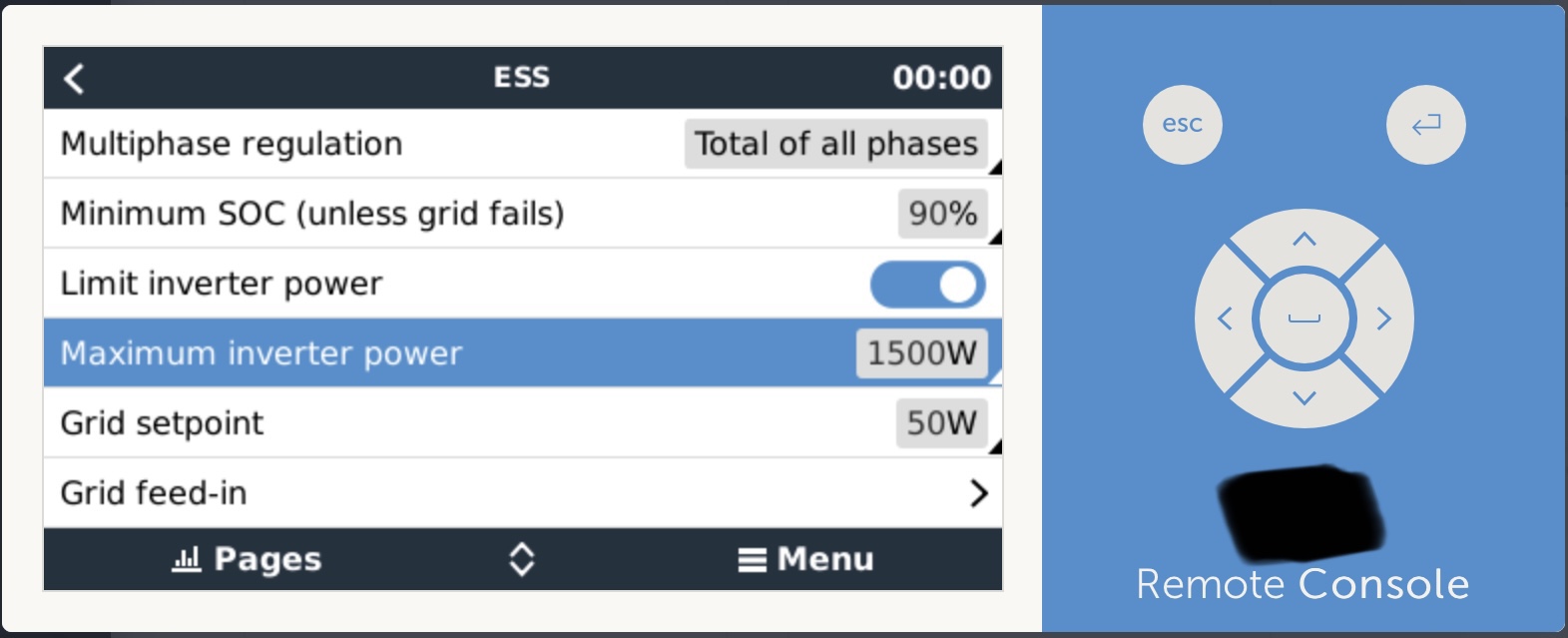
VEConfig3: Load current 7 A (1,5 kW - 400 W = 1,1 kW available for charging; 3 x 7 A x 50 V= 1,1 kW), lithium battery, ESS assistant with LiFePo4 with other type BMS, battery capacity 16 kWh, recommended values for BYD LVS
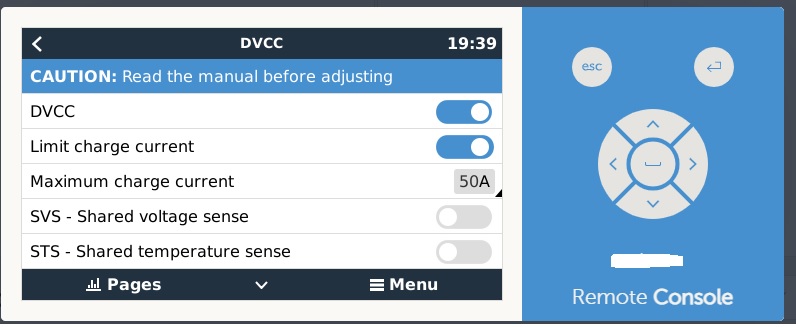
Cerbo GX set up: BYD LV on CAN-bus, DVCC on, load current limit 20 A, phase compensation, minimum SOC 20 %, shown active limit 50 %, grid set point 1100 W (= 1,5 kW - 400), PV-inverter no set up.

Question:
There is a set up possible according to Cerbo GX manual for limit charge power from AC1. In fact the Cerbo GX set up (2.62) doesn’t offer it. How can I activate it?
It would be useful to have it particularly in Germany, see targets and background.

How can I further optimize self-consumption during peak loads, e.g. increase de-load current of battery, or other actions?

Remark:
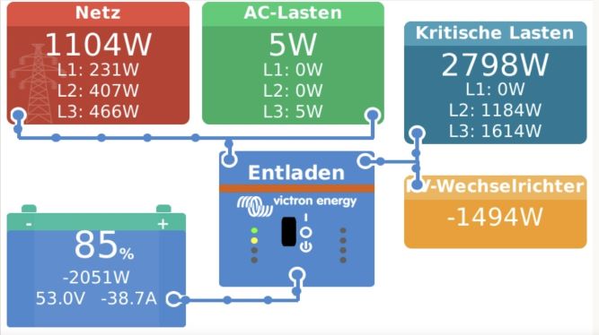
The data shown by Cerbo GX console and in VRM portal don’t make sense to me.
Examples: The information about grid, loads, PV-inverter and battery isn’t really balanced apparently PV-power is missing, historical value to grid and production isn’t zero in fact (see attachments).
What can I do to correct?
But one fact is clearly displayed: The minimum effect by the current from the battery.

screenshot-20210218.jpg

I would appreciate everybody’s support very much.

VRM-Report.pdf

cerbo gxESS
vrm-report.pdf (257.3 KiB)
2 |3000

Up to 8 attachments (including images) can be used with a maximum of 190.8 MiB each and 286.6 MiB total.

4 Answers
CristiMV avatar image
CristiMV answered ·

for limiting the charge current I use DVCC option

dvcc.jpg


dvcc.jpg (61.6 KiB)
2 |3000

Up to 8 attachments (including images) can be used with a maximum of 190.8 MiB each and 286.6 MiB total.

fred48 avatar image
fred48 answered ·

Yes, I set 20 A as limit for charge current to avoid charging from grid. I would need a hint by which set up parameters to increase discharge current.


2 |3000

Up to 8 attachments (including images) can be used with a maximum of 190.8 MiB each and 286.6 MiB total.

thomasw-1 avatar image
thomasw-1 answered ·

Hi Fred,
I cannot reproduce, why you want to limit charging current.

  • Battery is only charged, when no AC-loads have to be served.
  • In case of inverter capacity is higher than current AC-consumption, maximum power should be directed to load batteries
  • BYD LVS typically accepts up to 230A, whereas that level is mostly not reached. At the end of charging.phase BYD reduces automatically the current and prevents battery damages.
  • In case you setup such limit, you reach just the opposide, what you desire. In case AC-loads and max-charge current are below PV-production, rest will be fed into grid.

Btw. the highly chosen grid-set-point of 1.100W will also reduce overall PV consumption level. With that setting you force a minimum grid consumption level.

1 comment
2 |3000

Up to 8 attachments (including images) can be used with a maximum of 190.8 MiB each and 286.6 MiB total.

fred48 avatar image fred48 commented ·

Hi Thomas, thanks for your hints. The situation is that there is a yearly energy production of 13 MWh and a consumtion of 10 MWh in the system. In the ideal situation no ESS would be necessary. Unfortunately the reality is very much peak oriented caused by pumps, machines, heating, etc. Therefore an intellligent ESS is necessary to support the peak loads from the battary as much as possible and to re-charge the battery during low consumption phases from self-produced energy only.

As there is enough self-produced energy the ESS should use as low grid as possible and really no grid for charging. I tried to archieve this by setting the grid-set-point to 1,1 kW (= 1,5 kW self-produced power - 400 W constant base load) and to limit charge current to 21 A (= 1,1 kW available self-produced power for charging/50V battery voltage).

Where are the errors in my thinking with respect to Victron's ESS algorithms?

The critical parameter is the discharge current to maximize the peak load support. The capability of the battery is 250 A. The ESS only uses 80 A up to now. How can I manage an increase to, let's say, 200 A?

0 Likes 0 ·
CristiMV avatar image
CristiMV answered ·

The discharge current (actually power) you set via ESS...maximum inverter power...

1d5e4d60-7dd9-4e95-a8ed-d988fe80fdd6.jpeg


1 comment
2 |3000

Up to 8 attachments (including images) can be used with a maximum of 190.8 MiB each and 286.6 MiB total.

fred48 avatar image fred48 commented ·

There might be a misunderstanding. I don't want to limit the inverter power, i.e. the conversion from DC to AC. In opposite I want to increase it. The battery capacity is 16 kWh. The max discharge current is 250 A. In fact the max discharge current used in the ESS is 80 A. My question: How can I increase it, e.g. to 250 A?

0 Likes 0 ·