question

benm avatar image
benm asked

BMS Ve.bus 3 wire connector pin layout

I like to use the BMS ve.bus in combination with other cell monitor boards.

My cell monitor boards have only on single wire loop, this wire loop will be interrupted by LV and by HV.

My question: Will the BMS work correctly? I trigger the LV disconnect and HV disconnect?

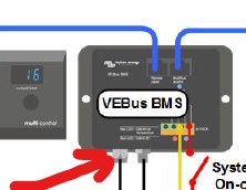
Is there a pin layout form the 3pin connector?


BMS
11 comments
2 |3000

Up to 8 attachments (including images) can be used with a maximum of 190.8 MiB each and 286.6 MiB total.

wkirby avatar image wkirby ♦♦ commented ·

Which 3pin connector do you mean? The circular M8 connector?

0 Likes 0 ·
benm avatar image benm wkirby ♦♦ commented ·

The cable that goes to battery.

0 Likes 0 ·
bms-plug.jpg (815.6 KiB)
benm avatar image benm wkirby ♦♦ commented ·

Retype question:

It will trigger the LV disconnect and HV disconnect?

0 Likes 0 ·
boekel avatar image boekel ♦ commented ·

There is a lot of talking in this topic, but I've not seen the basic question:

-what 'cell monitor boards' are you trying to use?

I'm pretty sure the Victron BMS wiring is a digital communication between batteries and BMS control unit, and I'm also pretty sure this is a closed protocol, so if you want to use this you'd have to reverse engineer it.
I'm pretty sure it's a digital connection as the BMS control unit (ve.bus BMS) is monitoring all batteries and sending commands to get them all in balance.

There is talking about LV/HV disconnect signals but I don't think this is how it works.

If I'm wrong about this please let it know so I can remove incorrect assumptions from my side ;)

0 Likes 0 ·
benm avatar image benm boekel ♦ commented ·

The cell boards I try to use have one single loop, that NC and will go open if there is a HV or LV. Or maybe I will build celboards myself. I search for how the Victron BMS input work and could not find. Thats why I ask this question. If they work as told below, I gone search for other solutions.

0 Likes 0 ·
boekel avatar image boekel ♦ benm commented ·

if they open both at HV and LV, you don't need a Victron BMS, you can just wire in a relay, and let the relay drive an input on the inverter, you run a 'two wire bms' assistant in the inverter. (you can configure for one wire in the settings)

Please beware: I don't know if and how other devices (like MPPT's) can listen to this (might work with DVCC?) so pleas make sure that works.


0 Likes 0 ·
benm avatar image benm boekel ♦ commented ·

To switch off a charger with a signal is not very safe. If a charger gives a too high voltage, there is probably a hardware failure (shorten FET) OR a failure in the processor. If this charger is the one that created a HV, than probably it can also not switch off with a externally signal!! So in a good design there need a other solution for this.

0 Likes 0 ·
Paul B avatar image Paul B benm commented ·

Keep in mind that on most boats (if we are talking about boats that is or if multi battery banks are in the system) there are House banks and Engine banks and Gen Banks. Usually connected using a diode/fet splitter system to stop cross feeding.

so opening the lithium bank will not cause large spikes as other batteries are still in the circuit.


Otherwise Ben please help everyone with a better design, so we can all get it write.

0 Likes 0 ·
benm avatar image benm Paul B commented ·

In my comment above I don't talk about spikes, only thing I commented is, to switch off a charger by a BMS signal is not safe.
It is better that in case off a HV that the BMS triggers a relay that switch off the AC side off this charger.

About spikes; you only get Voltage spikes if you switch off a battery from a alternators or charger that are producing amps at that time.

The Victron BMS has a separated HV and LV output, so if in a HV event, BMS cut-off the alternator(regulator voltage supply) and charger(AC side) and Solar controller(with a relay on panel side), the batteries are still connected.

My question in this post was how this BMS can be use with single cell boards. My conclusion is that if you use BMS with a single cell board, BMS will switch off the battery at HV, instead off, switching off only the chargers.

0 Likes 0 ·
boekel avatar image boekel ♦ benm commented ·

I'm not saying the bms has to turn off the charger if it goes to high, charger (and loads) should always stay in the 'safe' voltage range.

the BMS has to be able to shut down the system when there is an error in the battery.

Yes switching the AC side of the charger is very safe, but not my preferred method.

Mind you I very much prefer CANbus control, and combine this with a big breaker on the battery side with a trip unit activated by the BMS when things go wrong (overcharge / discharge / overtemperature) I do sometimes use a 'charge enable' signal to an alternator to be able to have lower (storage mode) voltages.

I also wouldn't advocate putting lithium banks and starter batteries on the same alternator, but in some cases it doesn't hurt.

0 Likes 0 ·
benm avatar image benm boekel ♦ commented ·

You wrote: "" I also wouldn't advocate putting lithium banks and starter batteries on the same alternator, but in some cases it doesn't hurt.""


Can you explain in which cases it will hurt?

0 Likes 0 ·
1 Answer
Paul B avatar image
Paul B answered ·

the cable has three wires black brown and blue

leave the black looped ( I think the black is for Temp but I have not used it)

if you open circuit the blue it triggers a LV disconnect

if you open circuit the brown it triggers a HV disconnect

blue maybe HV and brown LV cant remember for sure


If you only have one loop then join the blue and brown togeather at both ends and connect the loop inbetween, so if you get a open circuit from a Hi or low from the cell balancers the VE BMS will give load and a charger shutdown to the multiplus or quattro

anyway it works fine we have used it many times in our BMS

10 comments
2 |3000

Up to 8 attachments (including images) can be used with a maximum of 190.8 MiB each and 286.6 MiB total.

Paul B avatar image Paul B commented ·

I dont open the power wire as I am also using the BMS load control to drive a 400 amp load cut relay for other 12/24 volt loads. and you can use the charge cut off to open a relay that shuts the field off to the alternator as well or if you are using a balmar reg then the regulator.

0 Likes 0 ·
benm avatar image benm commented ·

For a loop you need two wires.

IF blue is LV, to which wire the loop is made?

Is the loop made to negative?? or to the third wire(black) in this connector?

Or could it be that the loop is from blue to brown? And that the BMS if detect a interruption in this wire, than compare with the overall voltage and make decision LV or HV disconnect.

Do you have a layout from the pins, if I order a BMS, it comes with NO cable.


0 Likes 0 ·
Paul B avatar image Paul B benm commented ·

the two 3 pin plugs one male one female. the wire supplied in the kit

cut it and it has three wires inside. so join blue brown on one and blue brown on the other.

link the blacks

0 Likes 0 ·
benm avatar image benm Paul B commented ·

But this means you have no separated load disconnect and charge disconnect?


0 Likes 0 ·
Paul B avatar image Paul B benm commented ·

I am sure our units come with a cable, if not you can buy the cables from victron. I know they come as a pair. in there packs.


I can send you the pn on monday if you need it

0 Likes 0 ·
Paul B avatar image Paul B Paul B commented ·

IF you only use say the blue in the loop and leave the brown connected the same as the black in the picture then you will only get a LV shutdown on the inverter

0 Likes 0 ·
benm avatar image benm Paul B commented ·

You mention brown and blue together, this means if I understand correctly, the BMS will activated the LOAD disconnect and the Charge disconnect, always at the same time. Is this correct?

Good to know how this wires to the BMS are working, Thanks.

You also mention a cuttoff relay for LOAD and relay for Charge disconnect.

But if you switch this relays the same time, there can be, that the alternator field switch off some milli secounds later as the LOAD disconnect. If this happen the alternator is working with NO battery connected. This means your diodes in alternator will burn.

0 Likes 0 ·
Paul B avatar image Paul B benm commented ·

well its not a perfect world, so this would depend on the BMS used.

if you leave the alternator connected to the batteries and not through the load relay then the HV disconect will not be a issue for the alternator and it will be disconnected through the HV relay via the alt field being disconected and loads would stay connected.

if you are using a single wire BMS then it could be a issue, but then better the alternator than the batteries I think

anyway MORE than likely if a system goes HV disconnect then the incoming amps will be way way down and its unlikely to do any spike damage ie from solar or the alternator. if you have a suggestion as to how to control the solar or alt shut off in a better way then please let me know.


I am all ears on this one, what do you do

0 Likes 0 ·
benm avatar image benm Paul B commented ·

I was looking how the Victron BMS could be used, for separated Load disconnect and separated Charge disconnect.

But with ONEwire loop cell boards it can not.

I need to search for other celboards, than the one I plan to use.


I was hoping that the BMS was working as the following:

If a discontinuity exist in the wire loop, the BMS compare with the Voltage that is connected on the BMS input. With this 2 parameters, BMS could make decision or it is a LV or HV event.

Technically it could operated like this, but it is not how it is designed.


If someone know a cellboard/balancer I can use with the Victron BMS that has separated, load and charge disconnect, please send me a message.

0 Likes 0 ·
benm avatar image benm Paul B commented ·

Your setup:

With one wireloop cell boards, you are using the Victron BMS as single wire BMS. A single wire BMS is very basic and can only switch of LOAD and CHARGE together. For the batteries it is safe. In this case it has NO function to switch off chargers/alternators with extra relays.


In this setup, the only way you can give alternators/chargers some protection is:

1 have a battery combiner(with voltage sense) in the system.

2 a extra Lead Acid/AGM parallel installed to the LiFePo4, and this battery switch should NOT switch off with the mainrelay. (Can be the starter battery)

3 a alternator protector like the APD12 from Sterling.

With option 1 and 2, alternator and chargers are continuous connected with a battery if BMS switch off the LiFePo4.

With option 3 chargers has no protection, from surge spikes.

With option 2 you have the advantage that if a BMS or something else fails, your important navigation etc will never be unpowered.

0 Likes 0 ·