question

nhenderson avatar image
nhenderson asked

Multiplus with switched AC inputs generator and mains

Hi, We have a system with Multiplus, SmartSolar MPPT, BMV and CCGX plus a custom switchbox for mains or generator input. The CCGX relay starts the genset based on battery SOC (different levels in normal or quiet hours) but it thinks the generator is the only input because of course the Multi has only one AC input.

(I know we should have bought a Quattro, but we were in a crisis and there wasn't one in stock within the timeframe, hence the custom solution)

The switchbox won't allow the genset to be started (despite the command from the CCGX) if there is mains power. This has the advantage that the genset shuts down automatically when mains power comes back, without any intervention from the Multi or CCGX. On the other hand, the CCGX won't close its relay to start the genset if there is AC into the Multi since the SOC can only fall below threshold if there is no mains power.

Would it be possible to program the CCGX to recognize two AC inputs, Generator and Mains, based on: if a generator start has been commanded the input is Generator; otherwise the input is Mains? I guess that would be a custom mod to the software and we would need someone to do that for us.

Other ideas welcome!

Multiplus-IICCGX Color Control
1 comment
2 |3000

Up to 8 attachments (including images) can be used with a maximum of 190.8 MiB each and 286.6 MiB total.

marvs avatar image marvs commented ·

It seems like your system is working the way you want it to so I’m not sure what having the CCGX recognize the input type does for you? Other than let you know if you were running off the GenSet or the mains, which you can probably tell for the recorded input data. Since the MultiPlus doesn’t care where it gets it’s AC input from I’m not sure what you are trying to accomplish?

0 Likes 0 ·
5 Answers
xavier-64 avatar image
xavier-64 answered ·

Hello,

after 3 days of reading and looking for some answers, that post is the one where I'm quite in the same situation with my RV.

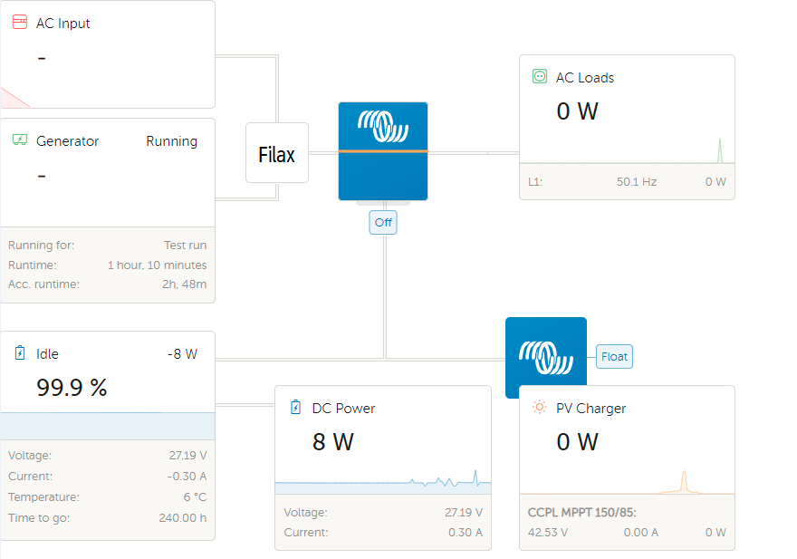
I have a grid/shore plug and a Genset device. The switch between Grid/Shore and Genset is done with a Victron Filax.

1673544527628.png

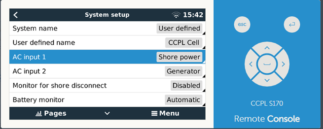
With the Cerbox Gx settngs, the settings of AC imput are like :
1673544594666.png

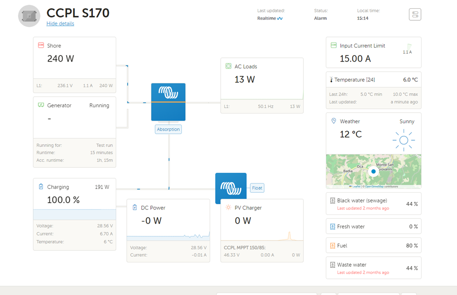
switching the settings of AC input 1 from Shore to Genset, the records are done correctly on VRM site and the picture animation too.

1673544678640.png


1673546705335.png

But, like @nhenderson@ceml.net If the Grid/Shore is plugged or is back, if the Genset is runing, the system is not able to detect AC real source and keep the genset on !

My wich is to be able to keep VRM recording AC input coming from the Genset or the Shore/grid distingily. And to be able to control the Genset either when the Shore AC is present.

Is there a way with the cerbox GX with the multiplus II to get 2 AC sensors reports ?

- In the way the cerbox GX and the multiplus are able to read AC inputs

- Or to bypass the internal AC detector by the external one to get AC inputs 1 and 2 identificable.

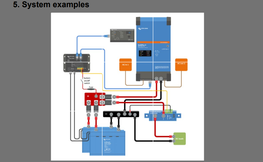
With my settings I also have the DMC control panel, Victron Lithium Battery with BMS and VE.BUS BMS device (not the last version neither the BMS Ve.BUS V2).

Like this one + a smartshunt + Cerbo GX

1673546037359.png


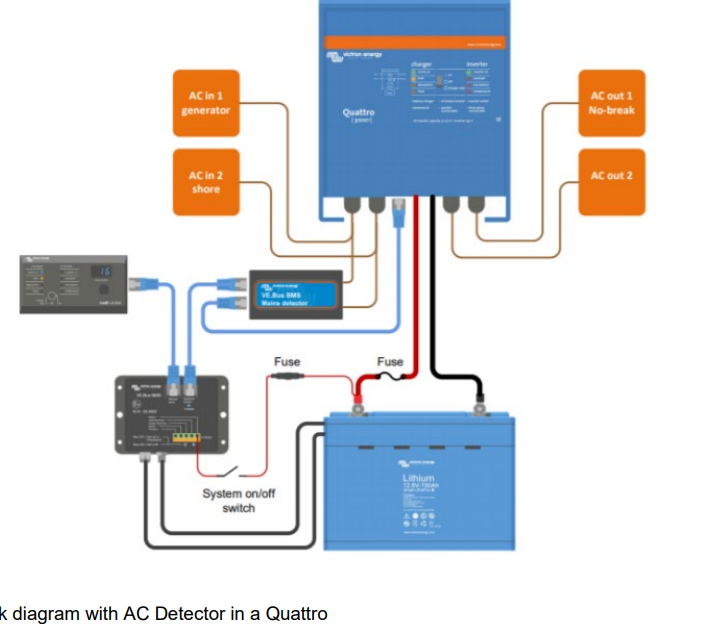
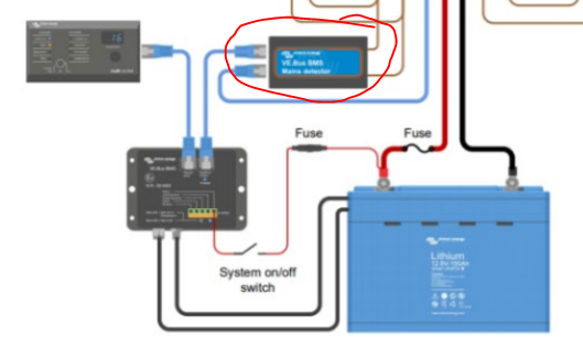
With the VE.BUS BMS, I have also emplemented the AC dectector like it must be done be only with multiplus or Quattro (not the Multiplus II or Quattro II)

The AC sensors are connected on Filax AC imputs.


1673546244625.png


Xavier


1673544527628.png (57.2 KiB)
1673544594666.png (54.2 KiB)
1673544678640.png (144.0 KiB)
1673546244625.png (173.7 KiB)
1673546705335.png (32.6 KiB)
1673546865886.png (178.1 KiB)
2 |3000

Up to 8 attachments (including images) can be used with a maximum of 190.8 MiB each and 286.6 MiB total.

Alistair Warburton avatar image
Alistair Warburton answered ·

I have looked at some of this... I only have AC1 set to Genset and found that even wnen AC1 was detected the genset wasnt marked as running.

My genset is manual start, at the genset so not intigrated at all.

As far as I can tell the genset running flag is only set if it is started by the system in auto or manual. My fix was to use Large OS Node Red to check the AC1 Voltage and mark the genset manual run or off accordingly.

This works well.

The Multi only has one physical AC in so enabling a second in the system OS is never going to report any load on that input, even fif the running flag is set. It may be useful for logging purposes though.

Your system has no digital inputs but the analouge input/s can still be used, with a small external circiit, to trigger the relay assistiant or drve a Node Red flow. I expect you could get some way to what you want buy reading the ststus of your changover switch an having that set he generator off when the grid is on!

Your the VRM screenshot shows the issue... No gen load and presumably when the gen is on and he mains is off he same state. I dont think yiu can change that but untime should update OK.

2 comments
2 |3000

Up to 8 attachments (including images) can be used with a maximum of 190.8 MiB each and 286.6 MiB total.

norman-and-audrey-henderson avatar image norman-and-audrey-henderson commented ·
Alistair, could you point me to some documentation about Large OS Node Red? Better still are you able to share your code to check AC voltage and set the genset status accordingly? I am wondering if I can check AC voltages on my (external, dumb) transfer switch and have the CCGX recognize if it has generator or grid input on that basis.
1 Like 1 ·
xavier-64 avatar image xavier-64 commented ·

Hello, thank for your time for the the answer.

I'm quite new with Victron use... So again thanks for this tips!


I just realyse that the screenshoot I gave was not the correct one but after swaping the AC name in Cerbo GX (he reason why tje picture is showing the GENSET up and runing and the AC input up too from the "shore".

By the way :


Ok I've quicly checked what Node-Red is ! Seems to be a interresting tool !!

If I can get information from the Mains AC detector of VE.BUS BMS device.


1673732503601.png

I think I will be able to handle something.

So I need to study that before validating the answer.

Xavier.


0 Likes 0 ·
1673732503601.png (88.3 KiB)
xavier-64 avatar image
xavier-64 answered ·

OK, Large OS Node Red is an interresting tool but I do not find the way to solve my trouble (missing ve.BUS main detector status). I will go ahead studing it.
In the meantime, I redraw/reformulate my question

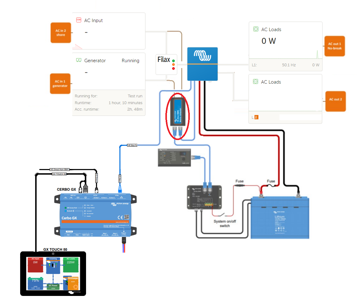
So I have focussed the draw with a new picture off my installation and linked with the request :

1673992584296.png

So the direct question is :

Is it possible to use the VE.BUS mains detector device to overwrite the Multiplus AC detection to the system or in other way with this schematic ?

Yes, the real issue is I want to use a Multiplus II as a Quattro II !!


1673992584296.png (231.9 KiB)
2 |3000

Up to 8 attachments (including images) can be used with a maximum of 190.8 MiB each and 286.6 MiB total.

xavier-64 avatar image
xavier-64 answered ·

So, In some way I found how to handle that by simple logic :

If the GenSet is On (Genset Relay OFF) it mean AC 1 must be setup as Genset input.

If the GenSet is OFF (Genset Relay ON) it mean AC 1 must be setup as Grid/Shore input.

With Node Red I can read the relay status but I do not find the way to change/update the System AC 1 input field accordingly

Still investigating !

2 |3000

Up to 8 attachments (including images) can be used with a maximum of 190.8 MiB each and 286.6 MiB total.

derrick thomas avatar image
derrick thomas answered ·

Kevin windrem's guimods and exttransferswitch mod will do just what you are looking for.

1 comment
2 |3000

Up to 8 attachments (including images) can be used with a maximum of 190.8 MiB each and 286.6 MiB total.

xavier-64 avatar image xavier-64 commented ·

Thanks ! Iwill look at it !

0 Likes 0 ·