question

Lyndsay Cotton avatar image
Lyndsay Cotton asked

Screen layout on VRM not showing AC2 out loads separately from AC1 out

This question may answer part of another question I posted two days ago.

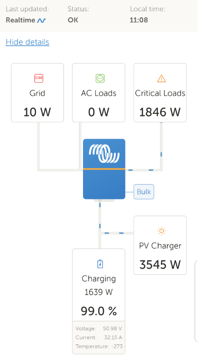
The VRM layout for the Multiplus 2 looks like the Screenshot document below


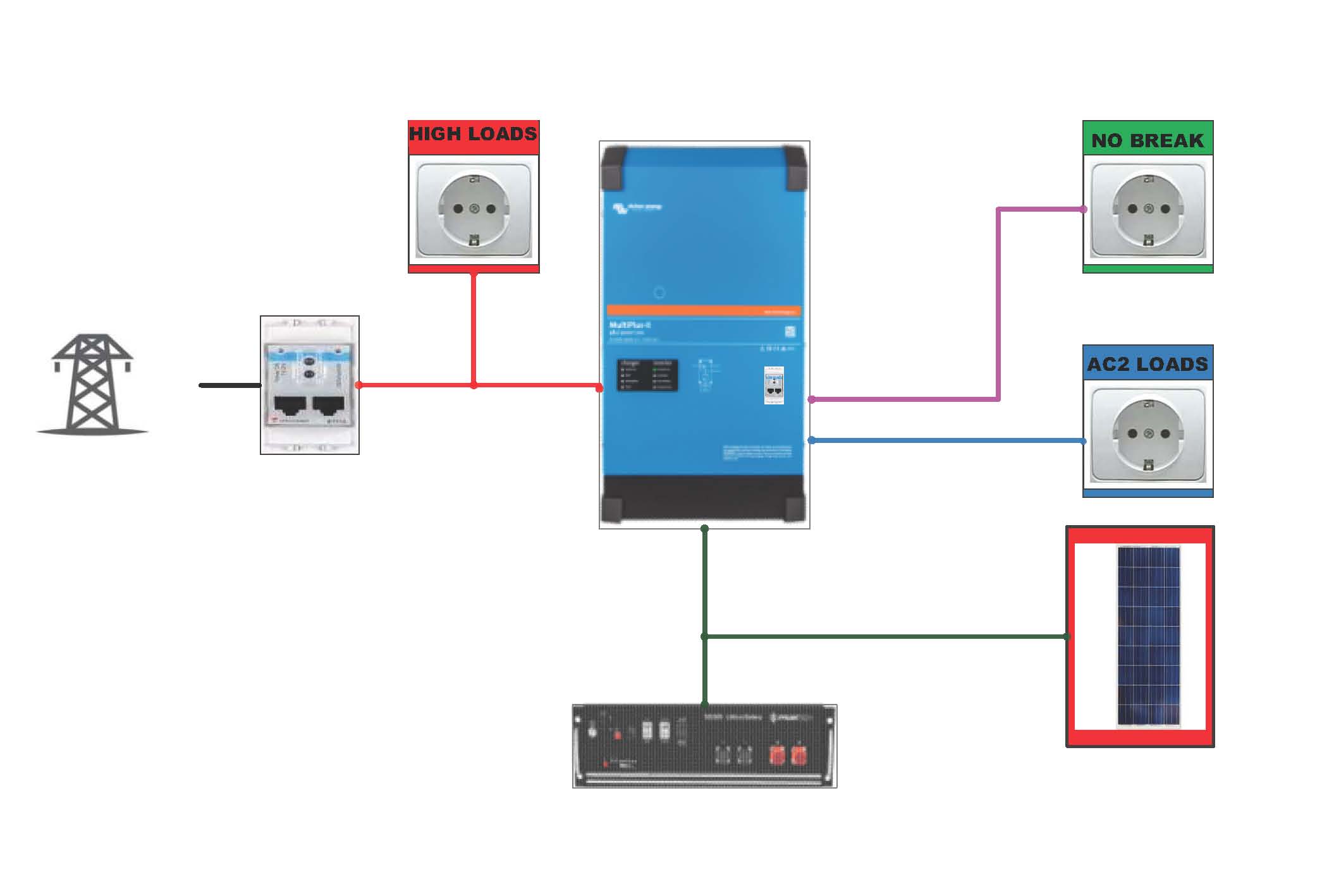
However, the second image reflects the actual layout

Surely the VRM portal (and remote console / Colour control) should rflect the actual statof the Multipluss wherein

AC1 = Critical loads (No break loads) - Green on image

AC2 = loads connected to AC2 of multiplus - Blue on image

"High loads" - Red load on Image


It is somewhat confusing as to what AC loads and Critical loads actually mean on the current VRM portal layout especially the "flow" of current depicted by the blue dashes.

Does "critical loads" (1846w for clarity) mean AC1 out and AC2 out

Does "AC loads" (0 w for clarity) mean the bidirectional load which is fedback into the grid but consumed by the "red" high loads?


vrm-snip-from-phone.pngvrm-layout.jpg

VRMremote console
vrm-layout.jpg (99.1 KiB)
2 |3000

Up to 8 attachments (including images) can be used with a maximum of 190.8 MiB each and 286.6 MiB total.

1 Answer
Guy Stewart (Victron Community Manager) avatar image
Guy Stewart (Victron Community Manager) answered ·

Hi @Lyndsay Cotton,

It is a limitation of the MultiPlus hardware that it cannot seperate AC1 out and AC2 out loads as independent measurements.

The power supplied to AC1 out and AC2 out are combined, and shown as such in VRM (and it can be no other way).

AC Loads in VRM, shown on the Grid side of the Multi are those loads that are communicated to the GX by an external energy meter (such as the ET112).

This allows the system to detect a difference on the AC input side between grid import, grid export and loads on the grid.

In your single line diagram example of your system, the multi knows how much it is pushing or pulling from the AC input, and thanks to the ET112 energy meter, it knows how much is coming or going from the grid. The difference between those two allows us to calculate the red 'high loads' on AC1 input as shown in your diagram.

If you want to see the AC2 loads, and measure them as separate to NO break / Critical AC1 output loads, then you should move those loads from AC2 out Loads, and instead have them connected to the AC1 input between the Multi and the grid meter.

They will then appear as AC loads in VRM.

7 comments
2 |3000

Up to 8 attachments (including images) can be used with a maximum of 190.8 MiB each and 286.6 MiB total.

Lyndsay Cotton avatar image Lyndsay Cotton commented ·

Thankyou - so in my screenshot above both AC1 out and AC2 out are seen as critical loads. Happy with the clarification.


I suppose I could add another ET112 to AC2 Out if I wanted to

In a hypothetical situation - could I add a number of ET112's to the system? - and control some high loads via the venus (and relay)

0 Likes 0 ·
Guy Stewart (Victron Community Manager) avatar image Guy Stewart (Victron Community Manager) ♦♦ Lyndsay Cotton commented ·

UPDATED - This is now available :)

old post -

It’s a common request, and perhaps some day, but for now you cannot. The energy meters are only selectable as grid (like you have it), PV inverter (for an AC PV solar inverter), or generator. You cannot just add extra energy meters and have the GX or VRM show you their readings as discrete AC circuit loads.


0 Likes 0 ·
hbo-electrical-contractors avatar image hbo-electrical-contractors Guy Stewart (Victron Community Manager) ♦♦ commented ·

Hallo @Guy Stewart (Victron Community Manager)

On a Quattro, with Grid Supply on AC1-in and Generator Supply on AC2-in,
can one install a meter on both inputs?

This will allow the client to see his Non-Essential loads displayed as AC Loads with Grid OR Generator supply on? Correct?

0 Likes 0 ·
Lyndsay Cotton avatar image Lyndsay Cotton commented ·

Following on then from the above - the following two questions

@Guy Stewart (Victron Community Manager)

Question 1:

1. Being multidirectional and the ET112 is placed in the position as per my schematic - ie: "Red" high loads being AFTER the ET112 but before the Multi - how does the Multi determine to feed back to the "Red" high loads if the Multi has been setup to NOT feed back into the grid?

This is not quite like a water pipe :) where a solonoid valve will close the pipe at the ET112 and allow the flow to the "Red" loads


Question 2:

2. Say it is a Multi 48/5000. This means that the continuous load should not exceed 4kw.

This will then be on a combination of AC1 (out) and AC2 (out). So I would design loads on the combination of AC1 out and AC2 out to not exceed 4kw

Does the bi-directional load (ie: the "feedback" load) not be part of this 4kw limit.

0 Likes 0 ·
Guy Stewart (Victron Community Manager) avatar image Guy Stewart (Victron Community Manager) ♦♦ Lyndsay Cotton commented ·

This all presumes that we are talking about a system programmed with ESS.

The 'grid' is defined as what is going through the ET112. So if there is a red load, it will be supplied by either the multi, or the grid.

If you set to zero export, no grid feedback, then the multi will want that ET112 reading to be zero. If it is reading a grid import to run the red load, the multi will push power to bring that grid reading back to zero.

In a normally operating system, there is no valve as such, it's a moving target, and the 'grid' import/export oscillate around that target it as the system dynamics (loads, charge sources, grid voltage, etc) charge, and the GX+ESS system adapts.


Q2 -

If the grid is connected and operating normally, then the Multi will do its best to supply all the loads that it can see, up to its rated power.

If the loads are greater than it's capacity, then it will supplement the rest with power from the grid.

If there is a grid outage, and there is no extra power available, then if you design the system to consume MORE than the rated capacity of the inverter, it will overload.

Unless...

The loads connected on AC1 input will be disconnected during a grid outage, so they do not need to be part of the consideration (in this factor of the design).

In a default configuration, AC2out is only connected when the grid is connected, while AC1out is permanent supply from the inverter. So if the grid disconnects, AC2out will be disconnected too. However, this control is programmable, so it's possible to allow AC2out to continue to supply in a grid outage.

0 Likes 0 ·
Lyndsay Cotton avatar image Lyndsay Cotton Guy Stewart (Victron Community Manager) ♦♦ commented ·

Hi, yes - using ESS

Q1. Thanks. Could we say then that the "Red" load is fed through the Multi but Not exported to the grid and the "control" is the path of least resistance.? For want of a better term.

Yip - I understand the dynamics and moving target as such.

Do I also understand correctly that the multidirectional feedback will ONLY happen if there is excess PV or;

Both excess PV and battery capacity?

We would surely not want to use the battery as feedback. That would defeat the designed topology of "Backup" critical loads only


Thankyou - I appreciate the time taken to answer in detail

0 Likes 0 ·
Guy Stewart (Victron Community Manager) avatar image Guy Stewart (Victron Community Manager) ♦♦ Lyndsay Cotton commented ·

The 'control' is voltage, so the Multi will raise its voltage slightly above grid voltage and current will flow out from the batteries, or PV, through the Multi to the loads.

Or it will lower its voltage and current will flow from the grid to the multi to the loads or to charge the battery.

If the Multi sees there is grid export (and that is set to 0), then it will reduce its voltage (and perhaps require also signalling to the MPPT to reduce it's power output)

The Multi will only 'feed-in'/export surplus PV to the grid.

BUT it will 'feed-back' through the ACin to the grid connected load that it can see from both PV and batteries.

The "Backup" is only relevant when the grid is out, at that point the ACin (red) connected loads are disconnected by the ACinput transfer switch.

You can set the state of charge level of how much of the battery you wish to discharge to loads (cycle), and how much you wish to keep in reserve (for AC1out connected loads) in case of grid outage in the ESS menu.

Or you can set the batteries to not discharge at all, and to stay charged 100% until there is a grid outage, even recharging from the grid (like UPS).

0 Likes 0 ·

Related Resources

Additional resources still need to be added for this topic