Edit: I changed the Digital Input Type from Door Sensor to Burglar Alarm. Some inputs send updates to VRM Portal on every poll and some send it on an event. With the Burglar Alarm type I can see the exact times my inverter switches ACOut2. Everything else in this guideline stays exactly the same. Note, the images have not been updated and still show the Door Sensor input type - used for reference only.
While I am also waiting on Victron to find time to add the ACOut2 Relay Status to VRM portal and the Modbus Registers I thought I'd use a workaround to get what I need.
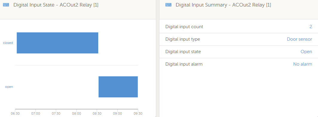
The following is a workaround to get a Quattro ACOut2 Relay status on VRM portal and also to check it via Modbus/TCP. Below is what it will look like.
What you need:
1. GX device with Digital Inputs. Refer to the following link to compare different models.
https://www.victronenergy.com/live/venus-os:start#comparison_table
2. Two to Six core Mains rated data cable depending on how many inputs you want to use, that you can legally use inside a distribution cabinet. I used some spare CBus Pink data cable that has an isolation voltage of 4KV. It has 4 cores but only used two for Digital Input 1 and Ground.
3. A suitable connector, to plug into your GX device's Digital Input port. I'm using a Venus GX and it requires a RJ12 connector. Refer to your GX device manual to see what is required.
4. A Mains rated DIN relay like a Hager EN146 Humfree relay.
https://hager.com/uk/products/h/en146-interface-relay-lv-vlv
Venus GX Setup
1. In your GX setup, go to Menu -> Settings -> I/O -> Digital Inputs and Enable Digital Input 1 and select Burglar Alarm.
2. Go back to the the Main Menu and you should see the Digital Input now visible on the GX screen. Go into the Digital Input 1 menu and select Setup. Make sure you Disable the Alarm notification and select Invert otherwise the state will show Alarm when in fact it's disconnected or unplugged.
3. Go one step back in the Menu and select Device. In this menu you can rename the input to EG. 'ACOut2 Relay'.
VRM Setup
At this point the new Digital Input should be visible on VRM Portal under Devices.
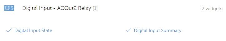
To setup VRM Portal to show the status you need to go to Advanced and then select the Widgets icon in the top right hand corner. Scroll down to the new Digital Input and select the two options as per below.
You now have VRM Portal reporting on the Digital Input 1 you enabled.
Wiring Setup
1. To wire everything together you need to install the Relay coil between ACOut2 and Neutral after your ACOut2 breaker. The relay will engage when ACOut2 is active and disconnect when you are in EG. Inverting Mode or any other mode that disconnects your main ACOut2 Relay.
2. Wire the NO/COM contacts of the new relay back to the GX device's Digital Input 1 using the mains rated data cable and you are ready to roll.
Final thoughts
I know this method is a workaround but at least you can monitor the state of the relay via VRM Portal as well as Modbus/TCP. In my particular case I wanted to know when it engages or not as I suspect a controller failure on my Quattro is not handling ACOut2 Relay as it should (fix in progress...)
To check the status of the relay using Modbus/TCP just connect to the GX IP address and use the Digital Input 1 ID and Register to read the Holding Register value. It should be either 6 or 7 as per the documentation.
https://www.victronenergy.com/support-and-downloads/whitepapers#
Disclaimer
I am not an electrician and any work done from the above suggestion is at your own risk and I am not responsible for any damage it might cause. If you feel you need verification or assistance with the above then please contact your Victron installer/reseller/distributor or electrician.