question

sebcbien avatar image
sebcbien asked

Wiring diagram for a van install with multiplus II

Hello,

After reading a lot those last weeks, especially here, (what a great help this community is !), I've come with a wiring schematics for my new van installation.

Years ago, I've already made a van installation with Victron lifepo4, BMS 12/200, BMV 712, battery protects and all went very well.

Now there is a lot of new products, protocols etc and I think that this wiring is the best I can think about.

I want it to be the simplest possible, with the less components.

I do not want to install solar at the beginning, I think I can only rely on the buck boost (I've a 250A alternator). I will maybe add them later if needed.

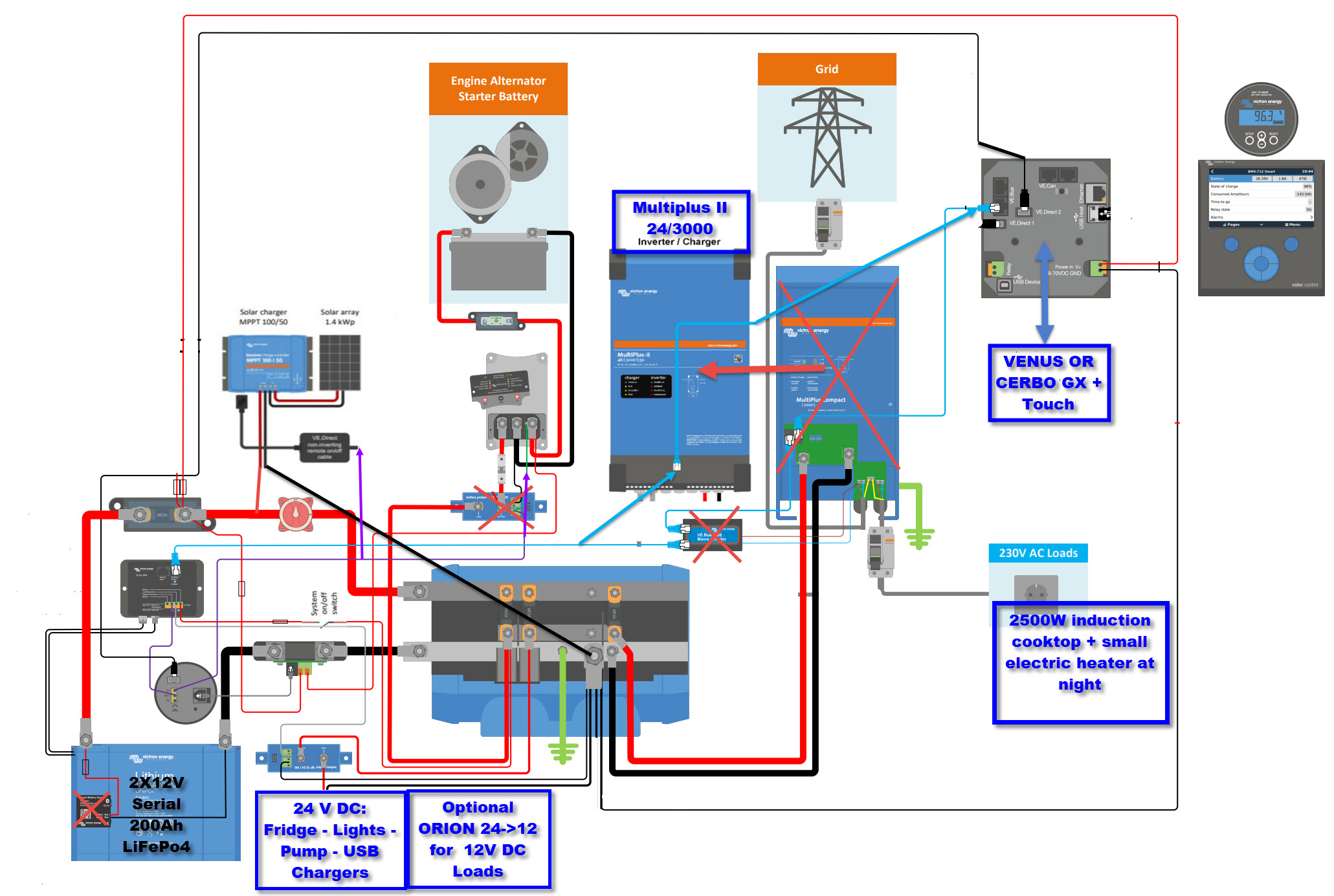
I used as a basis, the Victron van install diagram:https://community.victronenergy.com/storage/attachments/2524-van-full-wiring-diagram.png, removed un-necessary thing, added the Multiplus II 24/3000 and removed:

- Battery protect (charging)

- External temp sensor

- Isolation transformer

- AC detect (included in Multiplus II)

Do you think that this way the low temp security of the BMS will disable the charging from the Buck Boost, MPPT and Multiplus ?

Did I forgot something?

Do you see a better way to do it ?

Thanks a lot

(Tip: click the image link under the image or right click/open in a new tab for a better, full size image)

edit: 1) "typo" of the purple cable from BMS to MPPT 2) replaced the ve.direct to usb cable by a ve.direct cable to the GX

Multiplus-IIMPPT ControllersLithium BatteryBMS
2 |3000

Up to 8 attachments (including images) can be used with a maximum of 190.8 MiB each and 286.6 MiB total.

2 Answers
Matthias Lange - DE avatar image
Matthias Lange - DE answered ·

Looks good to me, but:
You still need the AC detector it is part of the BMS.
(It's function is to restart the BMS/Multi after a low voltage cut-off through the BMS if shore power is available)
The VE.direct non-inverting cable to the MPPT has to be connected to the "charge disconnect of the BMS.

I'm not sure why they use the relay of the BMV to switch the signal to the BuckBoost, maybe as a simulated D+ ?! IDK

2 |3000

Up to 8 attachments (including images) can be used with a maximum of 190.8 MiB each and 286.6 MiB total.

sebcbien avatar image
sebcbien answered ·

Thanks a lot Matthias, much appreciated !

Indeed, good catch for the "The VE.direct non-inverting cable to the MPPT has to be connected to the "charge disconnect of the BMS" it was a "typo" I updated the drawing.

For the AC detector, I cannot find it but I thought I had read somewhere that it was not needed for the Multiplus II

Edit: found it in the Ve.bus Manual -> https://www.victronenergy.com/upload/documents/Manual-VE-BUS-BMS-EN-NL-FR-ES-DE.pdf 4.1 AC Detector for MultiPlus and Quattro (included in VE.Bus BMS delivery). Not needed for MultiPlus-II models. The purpose of the AC Detector is to restart the MultiPlus or Quattro when AC supply becomes available, in case it has been switched off by the BMS due to low cell voltage (so that it can recharge the battery).

In the event of a low battery that has disconnected the Multiplus, if I start to charge via the alternator/buck boost to "initiate" the charge, will the Multiplus resume charging later ?

For "the relay of the BMV to switch the signal to the BuckBoost " I will make further research and report back here.

I also edited the wiring and replaced the ve.direct to usb cable to a ve.direct straight cable (enough connectors left on the GX)


4 comments
2 |3000

Up to 8 attachments (including images) can be used with a maximum of 190.8 MiB each and 286.6 MiB total.

Matthias Lange - DE avatar image Matthias Lange - DE ♦ commented ·

Ok, I didn't know about that. I never used a VE.bus BMS with a MP-II.

0 Likes 0 ·
sebcbien avatar image sebcbien Matthias Lange - DE ♦ commented ·

Do you know if it's the same problem with the buck Boost ? will it resume the charge after a low battery alert ?

Thanks !

0 Likes 0 ·
Matthias Lange - DE avatar image Matthias Lange - DE ♦ sebcbien commented ·

With charging sources (BuckBoost, MPPT) there should be no problem.
The "problem" with the Multi is that it will be turned off completely in case of a low voltage cut-off and it only can restart with the signal from the AC detector/BMS when shore power is available again.
The "charge disconnect" of the BMS is sill high in that case so any DC charging source can work.

0 Likes 0 ·
sebcbien avatar image sebcbien Matthias Lange - DE ♦ commented ·

GREAT !

Thanks, have a nice day !

0 Likes 0 ·