question

olesimo avatar image
olesimo asked

Victron Installation Review

Hi Everyone,


Have asked a few questions in the past with my ugly DIY install, have gotten lots of constructive feedback and finally got home so that I could rip it all apart and start over. Looks a bit less like kabalsalat, the worst of it that's left is the original Airstream wiring. For anyone that's curious, prior thread is here:

https://community.victronenergy.com/questions/58000/fighting-gremlins-electrical-cutoff-at-130-am.html

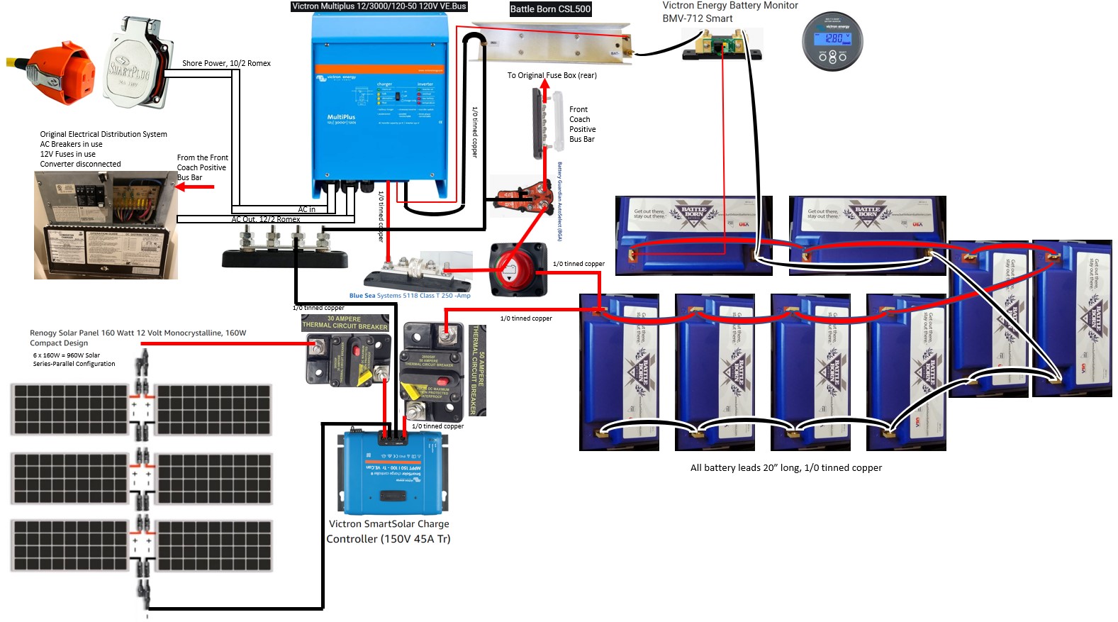
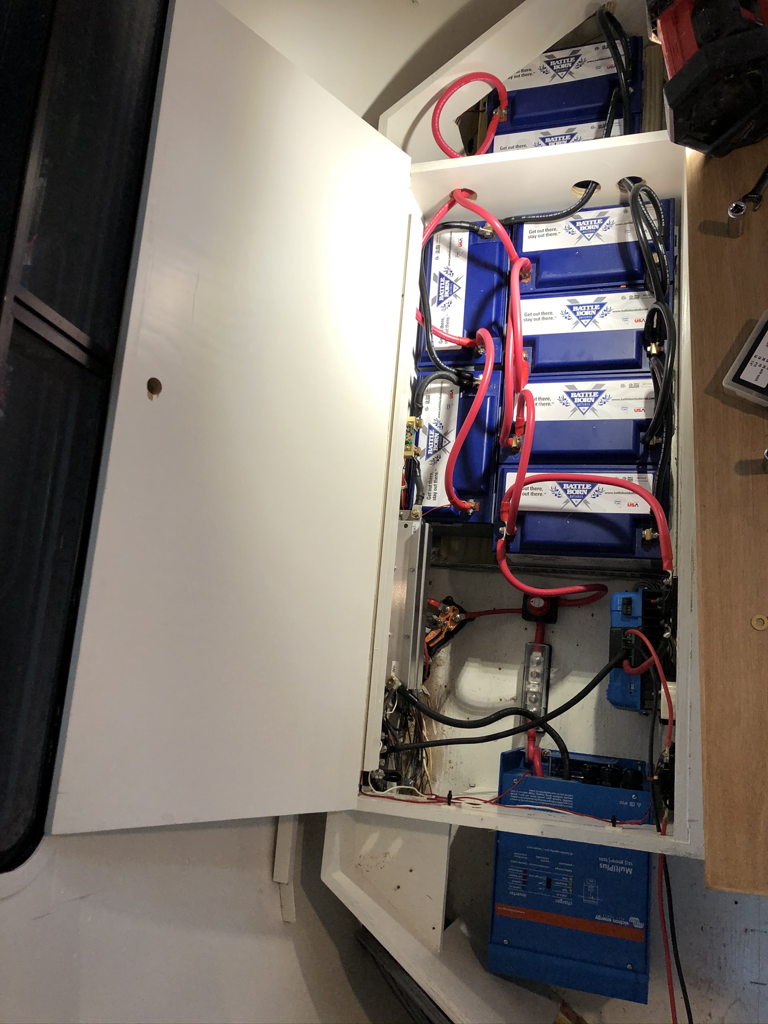
Here's a snapshot of the system today, completely reconfigured and rewired, upgraded the battery leads to 1/0 as recommended. Got rid of the massive industrial bus block, I think that was the main source of issues based on the condition it's in when I pulled it out, looks like two of the positive leads had worked themselves a bit loose. Added the battery disconnect per guidance, no-brainer that should've been there from the beginning. Lots of folks appear to put a disconnect between the MPPT and the batteries as well, but this seems redundant with the circuit breakers as you can manually trip the breaker and achieve the same goal.


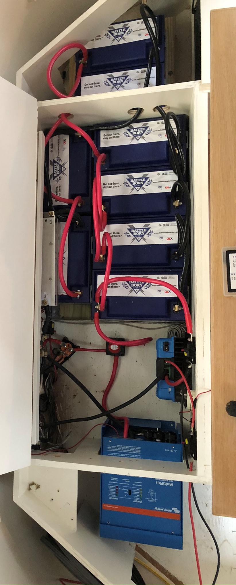
Couple of known items are to re-run shore power (no shore power included in this photo) and hook up two existing air circulation fans.


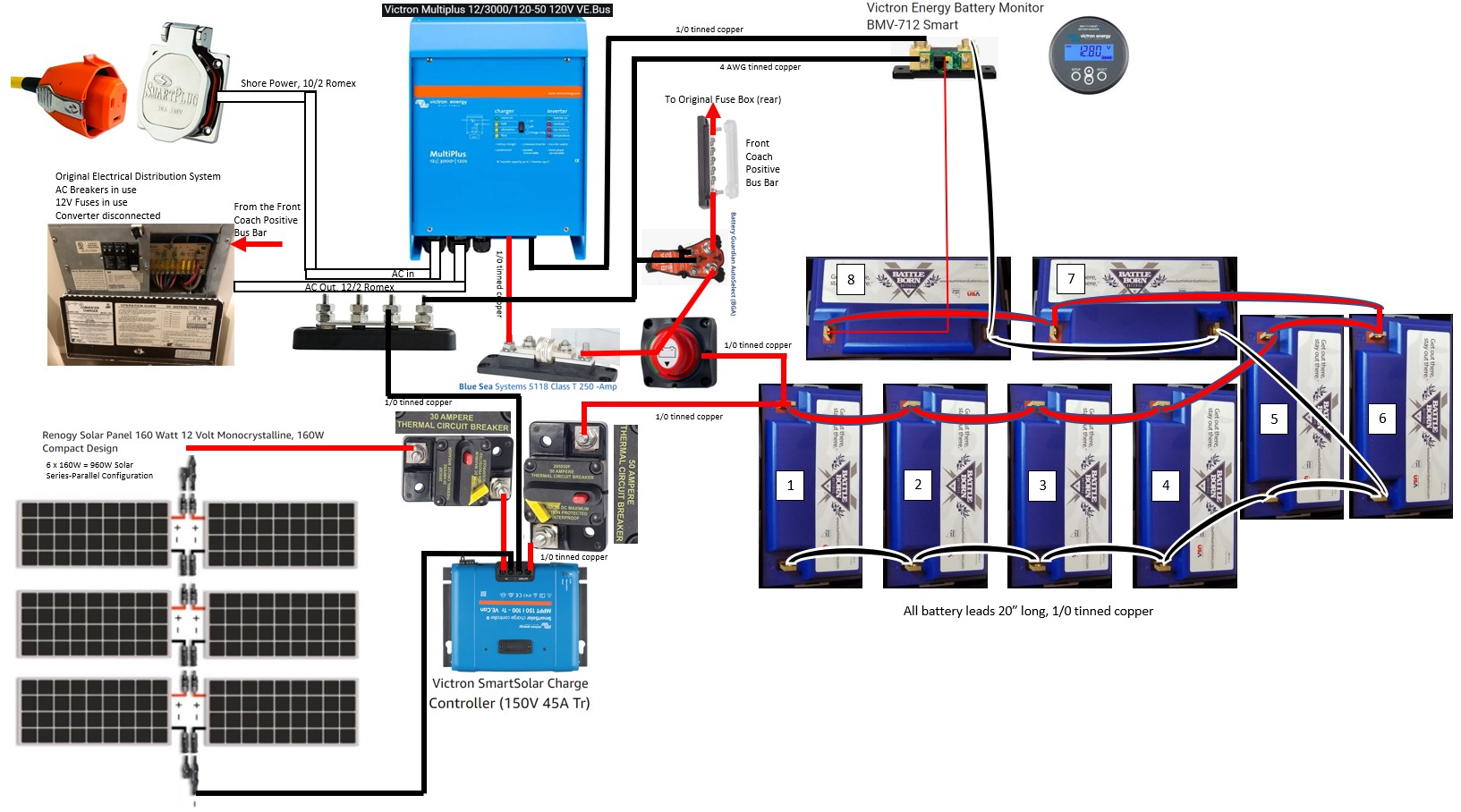
One more thing - hard to get a gauge from the photo, but all of the battery leads are the same length, 20". Tried to be efficient with the length, but it was a bit tricky since I have them in two different orientations to save as much space as possible. The negative lead is pulled off the top left battery, through the CSL, then the BMV shunt, then runs to the inverter. The positive lead is taken from the bottom left battery, straight into the battery disconnect, then to the inverter & BGA together, then positive bus bar for the DC loads.


Specific wrap-up questions:

  1. Am I missing any other disconnects? Various schematics seem to include one from the MPPT & tow vehicle trickle charger, but I don't see a point if the MPPT is protected by breakers and I don't have a trickle charger.
  2. Do I have the order correct on the negative side? Should it be CSL then shunt as I currently have it, or do I need to flip that? I know the shunt should be the first thing load-wise, but my reasoning was that the CSL doesn't draw anything on a stable basis.
  3. As I slim down my DIY'd and over-engineered system, I review the Multiplus specs and it looks like my Go Power automatic transfer switch is redundant with the built-in capability of the Multiplus. Is there any reason I should still include the Go Power automatic transfer switch when I re-run the shore power? I'm re-running a completely new lead & replacing the inlet, so it would be a convenient time to remove the transfer switch if it is unnecessary.


A bit about my system overall:

2003 Airstream
960W renogy panels, 6 x 160W each hooked up in Series-parallel configuration (two sets of 3 panels in series, then paralleled into the MPPT)
800 Ah BattleBorn batteries, 8 x 100 Ah each

BGA-225 battery guard
Victron Multiplus 12/3000/120-50 120v VE Bus

Victron SmartSolar Charge Controller (150V 45A Tr)

Victron BMV-712

Current Surge Limiter (CSL for short) (https://battlebornbatteries.com/product/current-surge-limiter/)

Go Power! TS-30 30 Amp Automatic Transfer Switch (likely to be deleted)

Multiplus-IIBMV Battery MonitorMPPT SmartSolar
img-3052.jpeg (375.1 KiB)
2 |3000

Up to 8 attachments (including images) can be used with a maximum of 190.8 MiB each and 286.6 MiB total.

2 Answers
the-doon avatar image
the-doon answered ·

Just a couple of things that stand out to me. I think the CSL should be only on the inverter negative with everything else before that. This device is purely there to limit the current inrush when you first connect a large inverter so the battery BMS doesn’t shut down. If for some reason this disconnects and you are charging via MPPT this could cause damage to the MPPT. Also I don’t believe the CSL is a replacement for a fuse so you should still have an appropriate sized fuse for your inverter and your other loads.

As for the MPPT, I use a circuit breaker on the solar input side and then a fuse on the battery side as again if you turn the circuit breaker off where you have it while solar panels are connected you could cause damage to the MPPT.

5 comments
2 |3000

Up to 8 attachments (including images) can be used with a maximum of 190.8 MiB each and 286.6 MiB total.

olesimo avatar image olesimo commented ·

Gotcha. I'll see about reconfiguring to get the CSL immediately before the inverter.


With respect to the MPPT, I see your point. From an operability standpoint, could also make sense if I commit to always tripping the solar source side before tripping the battery side, correct? Shut off the incoming source before the outlet, that way it doesn't fry the MPPT. Right?


Appreciate your time and input!

0 Likes 0 ·
the-doon avatar image the-doon olesimo commented ·

Yes that’s right, you always need to isolate the solar before the battery when disconnecting the MPPT.

0 Likes 0 ·
the-doon avatar image the-doon olesimo commented ·

Just out of interest, why have you installed the CSL? The documentation says it’s for 4kw inverters and above.

0 Likes 0 ·
olesimo avatar image olesimo the-doon commented ·

Touching a bit of an open wound there haha! I bought the batteries and inverter directly from Battle Born (Dragonfly Energy), asked about surge protection and was recommended this one. Being the OEM, I just took the recommendation for granted and bought it without as much research as I could've done. Now, having corresponded with them a few times, that's usually a question they ask as well, "why did you buy the CSL for this system, Simon?"


"Because you recommended it, darnit!"


Given that it's oversized, am I actually surge protected? Or do I need to resize this component as well to right-size for the application?

0 Likes 0 ·
the-doon avatar image the-doon olesimo commented ·

Sorry, missed this reply. It’s not a surge protector for the inverter so it’s not going to give you any protection there. It’s a surge protector for the battery BMS so it doesn’t switch off when the inverter is first connected. I’d be tempted to try the system without it and if no issues (which I think you won’t have) then ask to return it for a refund.

0 Likes 0 ·
Justin Cook avatar image
Justin Cook answered ·

@OleSimo, I'll mention a couple of things that strike me:

1. The MultiPlus should be connected to your battery bank with 4/0 cable and fused at 400A - this because the 12v Multi 3kVA can pull upwards of 380A under surge conditions. If you've fused your 1/0 cable appropriately to its maximum ampacity (285A, so fused at ~250A) then your circuit is adequately protected, but you'll definitely blow the fuse under heavy load, so better to correct that now. Currently I don't actually see a fuse(???) protecting the wiring feeding the Multi, which if true is a critical error that must be immediately corrected prior to powering this system up... particularly given that the Multi can pull far more current than that wire can carry, which means you have a recipe for melted wiring and possible fire on your hands. Required wire gauge and fuse sizing is found on page 8 of the MultiPlus user manual.

2. The MultiPlus transfer switch switches between shore and inverted power; your GoPower ATS exists to switch between two separate shore power sources (plug-in and generator), so if you plan to have more than one AC input then you still need an ATS or some kind of AC source selector upstream of the Multi.

If you get a moment, post a schematic of the system as it is so that we can double-check the layout and connection order of everything.

13 comments
2 |3000

Up to 8 attachments (including images) can be used with a maximum of 190.8 MiB each and 286.6 MiB total.

olesimo avatar image olesimo commented ·

You're completely right. I had a cheesy ANL fuse from Amazon that showed up and looked so crappy that I didn't even want to install it so I have returned it. It does look like most installations use ANL fuses so I'm debating getting a better brand name ANL fuse vs a T class fuse. I don't plan to fire the system up for at least a couple more weeks so I do have a bit of time.


I'll work on a schematic to help display everything. Appreciate the comments, including on the ATS.

0 Likes 0 ·
olesimo avatar image olesimo commented ·

@Justin Cook - Bay Marine Supply USA

@The Doon


Appreciate the feedback. I've incorporated the comments thus far - eliminated the ATS, swapped the CSL and the BMV, and added a T-class fuse between the inverter and battery disconnect. Also spent some time producing the wiring diagram below to reinforce the picture. Would love any additional comments or criticisms - trying to get everything dialed in before we leave for about a month of dry camping.


Airstream Solar Wiring Diagram.pdf

0 Likes 0 ·
the-doon avatar image the-doon olesimo commented ·

Nice job on the drawing. I’m not sure the negative cable between the CSL and the negative busbar should be coming from that side of the CSL. From what I understand after having a quick look at the CSL link is that it’s there purely to stop the battery BMS from cutting out due to the inrush of current that a 4kW and larger inverter capacitors would create. It’s a device designed to stop issues with inverters only so maybe swap that negative around?

0 Likes 0 ·
olesimo avatar image olesimo the-doon commented ·

@The Doon Thanks, probably should've made the drawing ages ago. Stupid question (while I contemplate the CSL): Any suggestions on a routing to connect the battery negative to the negative bus besides the way I currently have it coming off the CSL? Seems silly to pull it off the Multiplus with the other DC- terminal. Perhaps run it from the load side of the BMV shunt and skip the CSL?

0 Likes 0 ·
olesimo avatar image olesimo olesimo commented ·

While I'm at it...did a forum search for surge protection and didn't come up with much. Any recommendations on hardwired surge protection from shore power? Not a big fan of adding dongles outside, and I don't think there are any that are SmartPlug compatible anyway.

0 Likes 0 ·
Kevin Windrem avatar image Kevin Windrem olesimo commented ·

The CSL should only have the inverter connected to it's output. It's designed to precharge the inverter's capacitors to reduce connection current.

Negative bus connection order: battery -> shunt -> distribution (all DC loads) -> CSL -> inverter

I recommend keeping the CSL. Without it, the resultant current spike can shut down the batteries which isn't good for their internal protection circuitry according to Battle Born, and also could damage the DC power disconnect switch.

If you don't use the CLS, you should have a manual or automatic way to precharge the inverter's capacitors prior to turning on the DC disconnect.

0 Likes 0 ·
olesimo avatar image olesimo Kevin Windrem commented ·

@Kevin Windrem Thanks for the comments. I got a followup email and phone call from Battle Born this morning. Two different Battle Born reps have now recommended removal of the CSL (after a trainee Battle Born rep recommended installation last year). So I just finished pulling it out of the system, supposedly they will take a return after 14 months of being installed because I have it in writing that they recommended an unnecessary component. Unexpected level of customer service, goes a long way towards fixing a long term aggravation. They also pointed out that the wiring order for batteries 5 and 6 was incorrect, so I have fixed that now as well. V2 of the diagram is attached.


Their response for both the surge limiting to the battery as well as possible 'dirty' power from the shore power is that the Multiplus protects both for the wattage I'm running, especially with the BMS for the Multiplus-to-battery connection.


Last question (hopefully!) - now that the CSL is gone, the negative lead from the battery bank is approximately double the length of the positive lead. Will this cause a balance issue? Should I include some sort of loop on the positive lead to make the lengths equal?

Airstream Solar Wiring Diagram V2.pdf

0 Likes 0 ·
Kevin Windrem avatar image Kevin Windrem olesimo commented ·

Your cables are half the size Victron recommends for the 3000 va 12 volt Multi. They specify TWO 50mm2 cables for 5 meters and under and TWO 70mm2 cables for greater 5-10 meters. You will see increased voltage drop, heat and possible melting of the wires and stressing of connections wired the way you have it.

I also recommend a star connection to the batteries rather than daisy-chaining from one to the next. The energy pulled from the batteries won't be even wired the way you have it especially with long and undersized cables. If you do the star configuration, you can reuse your 1/0 cables from battery to common points but still need to double up from the common to the inverter.

The positive and negative leads do not need to be the same length. Total length of the path should be as short as possible though to minimize voltage drop.

Also, the 250 amp fuse is undersized as well. Victron recommends 400 amps for the 3000 va, 12 volt inverter.

BTW, don't forget to turn off the converter built into your AC/DC distribution panel. It will conflict with the Multi's charger in that it's powered FROM the inverter. When on batteries, the loop from inverter to converter to batteries and back will drain the batteries over time.

0 Likes 0 ·
the-doon avatar image the-doon olesimo commented ·

Good pickup on the battery wiring for 5&6. I did look at that area and thought something wasn’t quite right. As Kevin said no problem with that particular negative cable being longer. I just looked up the size cable you have used as well and it’s undersized as Kevin has said. The fuse will protect the cable but it’s not ideal. Can I suggest that you swap your T class fuse to the other side of the isolator so that it’s the first thing coming off battery one. This way it’s limiting the current for the whole system and protecting your cables. With some good power management you will get away with what you have but if you blow that 250A fuse it’s time to use bigger cables.

0 Likes 0 ·
olesimo avatar image olesimo the-doon commented ·

@Kevin Windrem, @The Doon


Agreed that the Victron manual recommends 4/0 wire with 400 amp fuse for the Multiplus. However, according to Battle Born, the wire size is driven by lead acid technology with much higher resistivity than the lithiums and Victron has not yet updated their tables for mass usage. According to Battle Born, their standard recommendation for their batteries with this exact Multiplus is the 1/0 that I've installed. The thing that didn't make sense to me is that they recommend 1/0 with the 400 amp fuse. While I'm clearly not an expert, seems like a 400 amp fuse would be pointless with 1/0 wire as the wire would burn before the fuse, may as well not fuse it at all. This is why I have matched the fuse size to the wire size to stay protected. As the Doon has said, if it turns out that I keep burning the fuse, then I would certainly upsize the wire and fuse together.


With regards to star connections, I haven't heard of that before. Perhaps I'm placing too much trust in Battle Born, but they have recommended the daisy-chaining, as have pretty much every RV/travel trailer installation pictures that I've seen. Is the star connection type intended for this type of application?


Kevin - agreed, I did disconnect the converter when I started this whole process.


Doon - I've debated the fuse location as well...agree with your point, I'll fix that as well.


Thanks again for all the detailed discussion, guys. First time working with DC power for any serious applications and it's been a steep learning curve.

0 Likes 0 ·
Kevin Windrem avatar image Kevin Windrem olesimo commented ·

It's wire ampacity that's a factor regardless of the battery type. 1/0 is good for 170 amps if the insulation is rated for 90 C. 3000 VA would draw 300 amps plus an efficiency factor so you'd need TWO 1/0 in parallel which is what Victron recommends. 4/0 would get you to 260 amps at 90 C. There are marine cables rated for higher temperatures. 105 C gives you a little under 200 amps.

250 amps on 1/0 cable will run over 200 C.

You can get a good idea of power balancing between batteries with your current wiring. Just pull a load from the inverter and measure the voltage across each battery. That will give you an idea of voltage drops in your cables and using that you can calculate currents in each leg based on wire resistance. Star connection will eliminate all voltage differences. BTW, you can reuse your 1/0 cables from each battery to the common star point as each leg will then be 1/8 the total current.

0 Likes 0 ·
Kevin Windrem avatar image Kevin Windrem commented ·

You should really star-connect your batteries. "Daisy-chaining" them as you've done especially with "small" wires won't balance battery usage properly. Use bus bars to connect each battery to a common then run the recommended wire size to the inverter (check the inverter manual).

0 Likes 0 ·
Justin Cook avatar image Justin Cook ♦♦ commented ·

@OleSimo, it looks like others have covered most of the things, but I'll reiterate one point in particular: 4/0 and a 400A fuse, not 1/0... this is to do with ampacity, nothing to do with resistances of Pb vs LFP batteries. If you use high-quality marine-grade 4/0 like Ancor wire, it can carry 445A outside of an engine space, so can safely be fused at 400A, which you want because the Multi, under surge conditions, can pull ~387A (observed on my test bench). You can use lesser wire as long as you keep your fuse under the wire's maximum ampacity, but you run the risk of blowing the fuse if you load up your Multi.

I'll also note that the Bussman Series 285F circuit breakers you show are only rated to 48vDC nominal, so a maximum voltage of ~56v; this is fine on the output side of the MPPT, but is not fine for the PV side where 3 panels in series will likely have a VOC of around 90vDC or so. For the PV side of the controller, you should use a MidNite Solar MNEPV breaker (rated to 150vDC) or similar.

Using the "diagonal" method of parallel-connection of your battery bank is fine; with this many batteries I would prefer to see the busbar method, but this is still a perfectly valid method.

0 Likes 0 ·