question

texascharlie avatar image
texascharlie asked

Do I need a circuit breaker?

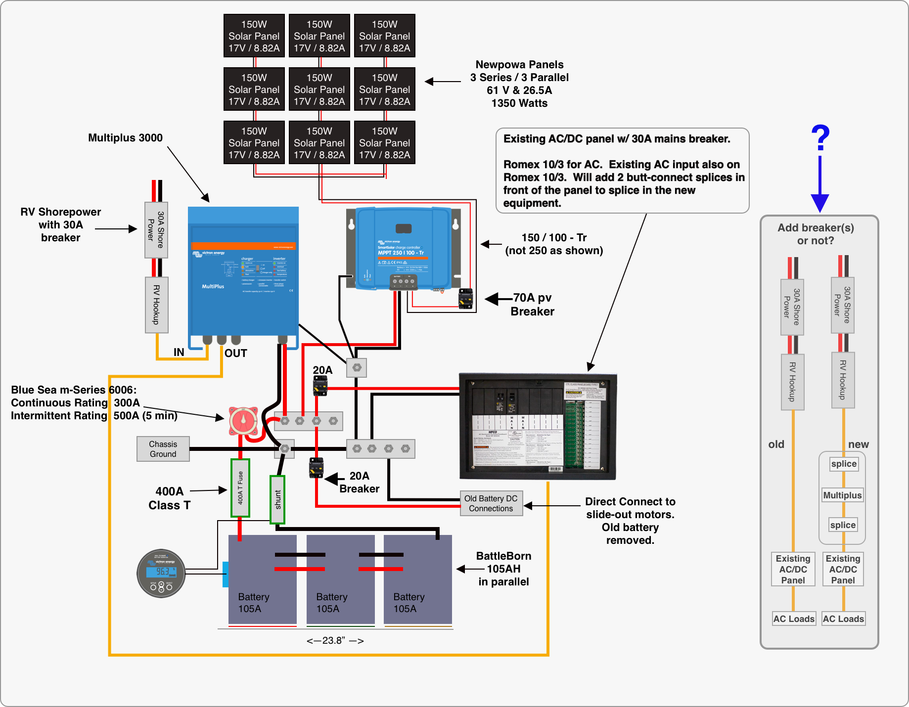
I'm putting together plans to add solar to my RV and I think I have figured out what I need, but have one open question. I'll be splicing-in the the new power system to the existing AC input line.

Question is: do I need a 30A circuit breaker added to my schematic? The shore power will come out of a 30A breaker, and there's a 30A main breaker on the existing AC/DC distribution panel.

So is it necessary to add yet another breaker where I'm splicing-in the Multiplus?


Multiplus-IIGeneratorwiringwiring diagram
2 comments
2 |3000

Up to 8 attachments (including images) can be used with a maximum of 190.8 MiB each and 286.6 MiB total.

Joshua Warren avatar image Joshua Warren commented ·

One other thing: I personally have not had good experiences with DC circuit breakers. If your experience has been different then by all means go ahead with them, but in my experience the manufacturing tolerances just aren't that great. I put a 3kw inverter in my truck and initially wired it with a 300A DC breaker; it would trip at 220-230A every time, and I had a similar experience with a 60A DC breaker for another inverter install years ago. Since then I've used fuses for everything on the DC side and if I need a disconnect then I just put a switch in series and call it a day.


If I've just been unlucky and you can recommend reliable DC breakers please say so (and let me know which ones actually work), because there have been plenty of times in which it would have been advantageous to use such a device rather than a big clunky switch and fuse block but I went with the clunk just to avoid the potential for drama.

0 Likes 0 ·
Elimac avatar image Elimac Joshua Warren commented ·

Telecom companies use some series of standard DIN rail breakers, but only some support DC, and only up to 125A. My personal preference: Schneider iC60H/C120H.

0 Likes 0 ·
3 Answers
Kevin Windrem avatar image
Kevin Windrem answered ·

Technically, the breaker in the pedestal outside your RV will provide protection for the internal wiring, but I recommend adding a breaker inside the RV ahead of the Multi. There are times when you may hook up to a 50-amp service and the 10 gauge wire is then not protected.

Do NOT use crimp splices on romex or other solid wire. Crimps on solid wire can work loose with any vibration. A screw terminal strip or at least wire nuts provide a much better connection.

There should be a fuseor circuit breaker in the connection between your busbar and the MPPT. This is to protect the wiring should short to ground.

Not sure, but 20 amps may not be sufficient to power your DC distribution. These typically have at least a 30 amp circuit breaker at the battery. The panel should have one or more main fuses and I'd use that for your breaker size. Make sure the wire to the panel is of sufficient size.

You may get some imbalance in the current to/from each battery due to voltage drops. Taking the negative from one battery and the positive from another is perfect with two batteries but with three, there could be some imbalance. It's suggested to connect each battery to a busbar or post, then to the loads. You can probably use the shunt's battery connection for the 3 battery cables and likewise use the battery connection of the fuse for the positive battery cables.

A smaller breaker for your PV array would provide better protection. But as long as the wire is sized to handle the short-current of the array you really don't need a fuse/breaker. The difference between max power current and short circuit current of most solar panels is not significant.

You can combine the post and busbar in the negative DC path. Also, check the wiring to your existing DC distribution. It may also have a chassis connection and you should really only have one.

Have fun.

1 comment
2 |3000

Up to 8 attachments (including images) can be used with a maximum of 190.8 MiB each and 286.6 MiB total.

rubicon avatar image rubicon commented ·
What brand and model breaker do you recommend before the main into the inverter?
0 Likes 0 ·
Joshua Warren avatar image
Joshua Warren answered ·

I second @Kevin Windrem's concerns about the limit on the DC loads. I think you'll need considerably more than what you've spec'd. The furnace air handler will pull about 10A; then add in some lights, etc. Individual slide-out motors can easily pull 25-30A, and if they're running simultaneously...you get the idea.


In an RV application you will often be in partial shade, so just make sure you consider that effect on the PV array. On my fifth wheel camper I installed six 200w panels -- each with its own MPPT -- to eliminate that issue entirely.


Also, this design doesn't take advantage of, or actively defeats, one of the things you're paying for with the Multiplus: power assist. The Multiplus can supplement AC input by inverting from the batteries to sustain short-duration / high-current loads. Make sure you understand this feature before proceeding with your build. I would personally recommend replacing the 30A panel in the main breaker with a 50A breaker and wiring the Multiplus to the panel with 6 AWG. The 10 AWG to the multiplus from the power inlet is fine, but -- to answer your original question -- I would put a 30A breaker between that inlet and the Multiplus, especially if you do as I recommend and wire the main panel for the 50A to capitalize on power assist.

2 |3000

Up to 8 attachments (including images) can be used with a maximum of 190.8 MiB each and 286.6 MiB total.

texascharlie avatar image
texascharlie answered ·

Jersey & Kevin,

I appreciate the thorough replies and will update my plan accordingly!

4 comments
2 |3000

Up to 8 attachments (including images) can be used with a maximum of 190.8 MiB each and 286.6 MiB total.

Kevin Windrem avatar image Kevin Windrem commented ·

I agree with Jersey about upgrading the input to the AC distribution to the max the current panel can handle. Check the manufacturer's specs. The WFCO models are rated for 30 amps max until you get to the 120/240 volt models.

Relying on power assist allows the inverter to kick in to handle additional load while on shore power however you need to manage loads when shore power isn't available to prevent overload. This includes momentary shore power dropouts.

Make sure you disconnect the battery charger in your power center. With the inverter connected ahead of the power center as you've done, the inverter will power the charger which will draw current from the batteries if not on shore power. You'll drain your batteries because the process is not 100% efficient.

Disabling the charger can be done by disconnecting the AC input to the charger. You'll find a wire from the charger connected to one of the AC breakers. Just disconnect that wire or if its on it's own breaker, just turn that one off.

0 Likes 0 ·
Joshua Warren avatar image Joshua Warren Kevin Windrem commented ·

Good call. I recommend switching off the breaker but leaving things intact so if something goes awry with the inverter you can bypass it and rely on the old converter for 12 VDC on shore power while you deal with the problem.

0 Likes 0 ·
Kevin Windrem avatar image Kevin Windrem Joshua Warren commented ·

That raises another issue: If the inverter is off (or fails), AC output goes away. Victron says this is done for safety.

I added a bypass switch around the inverter so that if the inverter fails I can still have AC to the RV.

This could also be done with a relay that's energized by the inverter but at the expense of a small amount of additional power consumed while on inverter and no shore power.

1 Like 1 ·
Joshua Warren avatar image Joshua Warren Kevin Windrem commented ·

I did something similar but less elegant. I made the entire installation modular; i.e., downstream of my 50A breaker (inside the camper but upstream of the inverters), I have two NEMA 14-50 receptacles. Downstream of the inverters but upstream of the panel I split the input into two 14-50 plugs (each with opposite "line" prongs connected to each of the L1/L2 inputs to the panel). My inverters' inputs and outputs have 14-50 plugs and receptacles, respectively (I could have used single phase plugs/outlets for all this but I wanted to keep everything consistent with RV standards to ease debugging). So essentially the inverters are just "in between" the outlets and the inlets, and I can completely bypass the entire system by just unplugging the inverters and plugging the panel input plugs into the two receptacles downstream of the 50A breaker. When I set this up I was imagining a scenario in which one/both of the inverters had to be serviced or was out of the camper for a few days, so it seemed more flexible (but less pretty and with greater space requirements) to be able to just plug/play. Hopefully I never make use of that "feature."


I also have a 14-50 Y-adapter (one plug, two receptacles) so if I lost one inverter I could quickly reconfigure the system (no rewiring, just unplugging/replugging) to run on single pole 120V with just the one inverter.

0 Likes 0 ·