Greetings, this is my first post here, so hopefully this does not reveal me to be a complete moron. I recently set up a power system (VRM link) in my fifth-wheel camper consisting of the following:
2x 300 AH Victron Smart Lithium batteries,
2x Multiplus 3kva/120 inverters in 120/240 VAC split phase,
2x SBP-220s (one as a load disconnect and another as a charge disconnect, as there are multiple DC charging sources),
6x Smartsolar 75/15 MPPTs with a 200w/24V nominal panel connected to each,
Orion-Tr Smart 12|12/30 DC/DC charger,
BMV-712 with shunt,
VE.bus BMS, and
Cerbo GX with GX Touch 50 display
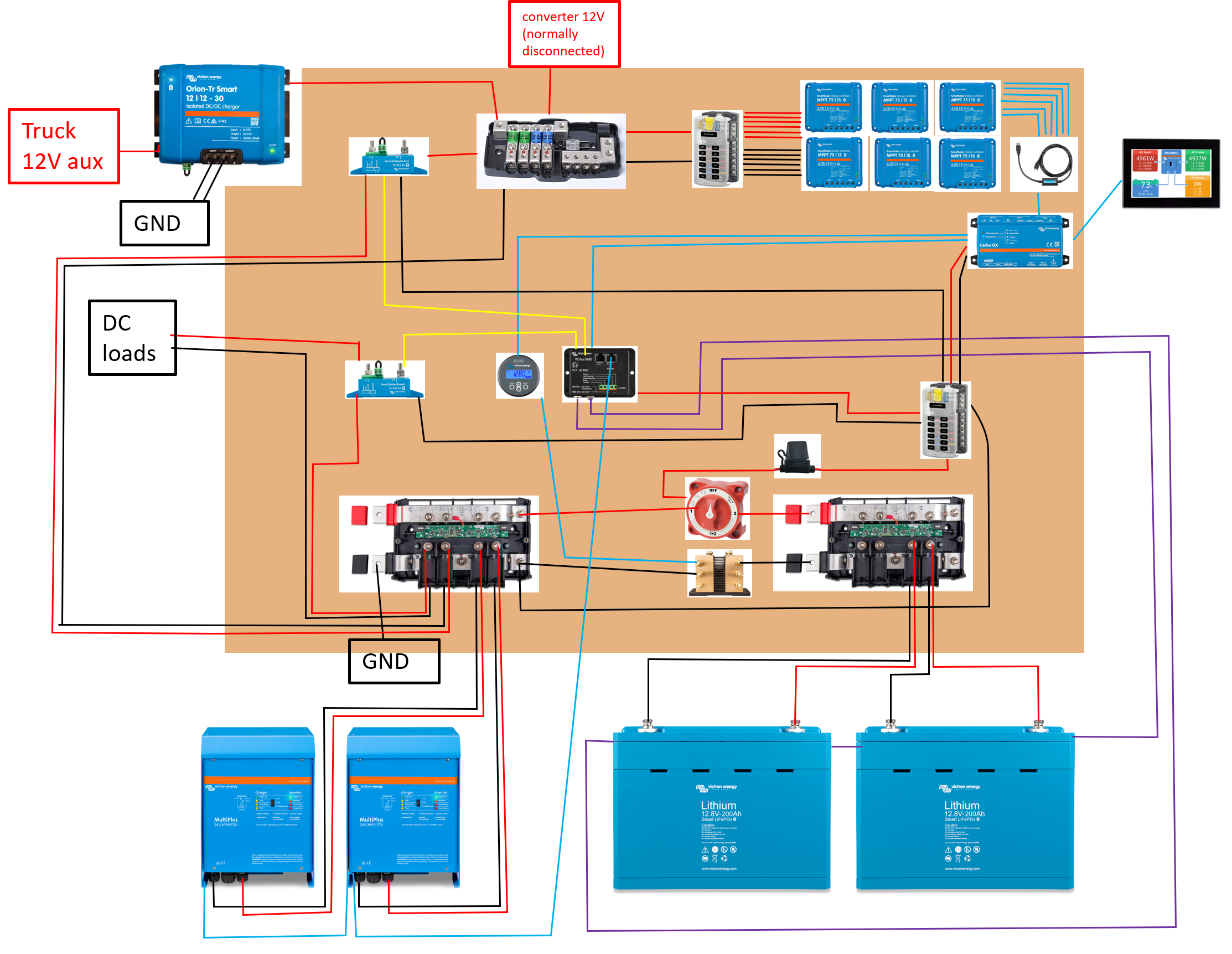
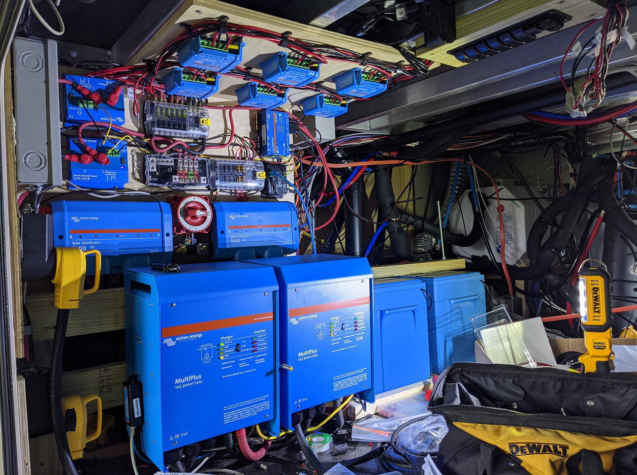
(I've included a picture of the system as well as a rough diagram of the connections as well -- I know the mounting of the MPPTs looks suspect but there is a large circular hole drilled in the plywood behind each for ventilation, and there are about three inches of clearance between the plywood and the ceiling above it)
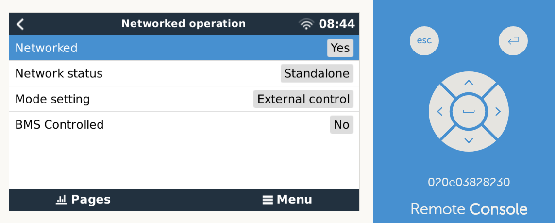
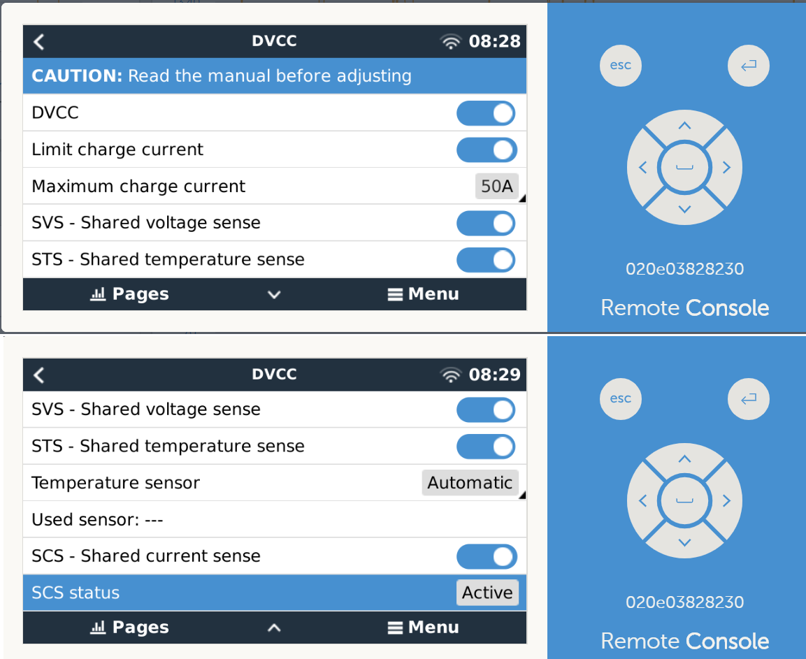
The MPPTs are connected to a USB hub which, in turn, is connected to the Cerbo. Everything seems to be recognized just fine and I can see all the system parameters in both the Cerbo's menu and VRM. DVCC is enabled (see screenshots below).
I have the following questions:
1) The MPPTs' charging states did not appear to be exactly synchronized, so I set up a VE.smart network between them. Then later I learned about DVCC and enabled it. What is the proper way to synchronize the MPPTs (and the inverters and Orion charger, if possible) in this configuration? As you can see in the VRM screenshot the inverters and the MPPTs are not in the same charging state. Did I screw this all up?
2) I do not have a temperature sensor currently installed, because I assumed that since the batteries measure their temperature internally that they would report this information to the BMS which would, via VE.bus, communicate it to the rest of the system. But now that I've looked at the cables I see that that there are only three conductors between the batteries and the BMS; perhaps one is ground, one is charge disconnect, and the other is load disconnect. I have the temperature sensors that came with the inverters but I do not have the one that is compatible with the BMV (https://www.victronenergy.com/accessories/temperature-sensor-for-bmv-702 ) -- is there an advantage to getting the latter or should I just use one of the inverter sensors? Is there some other/better way to do this?
3) One of the goals for this system was to be able to function as a UPS for two 15 kBTU/hr air conditioners (one on each phase). The inverters are currently set up with "switch as group" unchecked because the trailer will sometimes have a 120/240 VAC connection and at others it will only have a 120 VAC (i.e., zero line-to-line voltage) connection. In this configuration with "UPS function" disabled, if I have the two air conditioners running and cut the AC input, both inverters will throw an overload. What then seems to happen is they make attempts to restart at 30-second intervals, and generally on the third attempt they're successful and the air conditioners start back up. If I instead enable "UPS function", I can cut the AC input and the inverters will maintain power to the air conditioners without interruption. However, in this case, the system will not recognize single-phase 120 VAC input so even when such input is connected they will continue inverting. They will only recognize the 120 VAC input if I disable "UPS function", but then the overload problems occur. What's bizarre to me is that whether "UPS function" is enabled or disabled, if I am running the system without AC input (i.e., inverting), I can start both air conditioners without overloads. The overload only occurs if the air conditioners are already running when the AC input is suddenly cut and "UPS function" is disabled. I have used a multimeter to measure the DC voltage difference at the batteries and at the inverters when I cut the AC input with the air conditioners running; it does not get even close to the "DC input low shut down" value, and there's no perceptible voltage difference between the batteries and the inverters (i.e., I don't think it's due to poor connections -- and all inverter and battery cables are 4/0). Is there a way to get the fast-switching that seems to prevent the overload from occurring while also retaining the ability to use 120 VAC and 120/240 VAC inputs interchangeably?
Any thoughts on any of the foregoing questions (or general comments/recommendations on the configuration or layout of the system) would be most welcome (I know the wiring is a bit of a mess; still finalizing things). Or if you're just generally facepalming at this setup please let me know that as well -- I'll take harsh feedback over burning up $15k USD any day!
