question

dayandnight avatar image
dayandnight asked

Multiplus-II GX Current sensor for Grid-based PV

Hello Victron community,

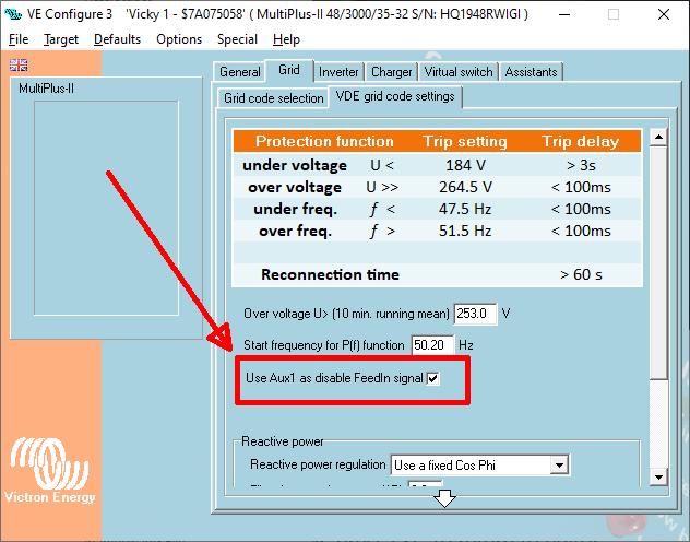
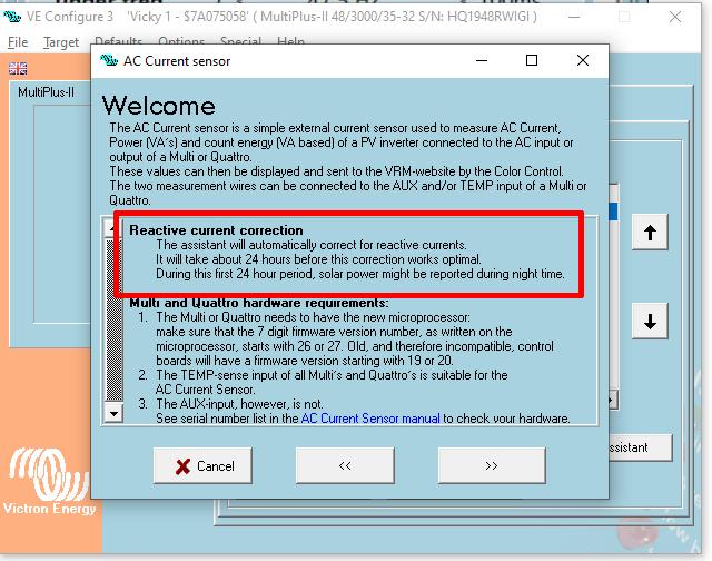
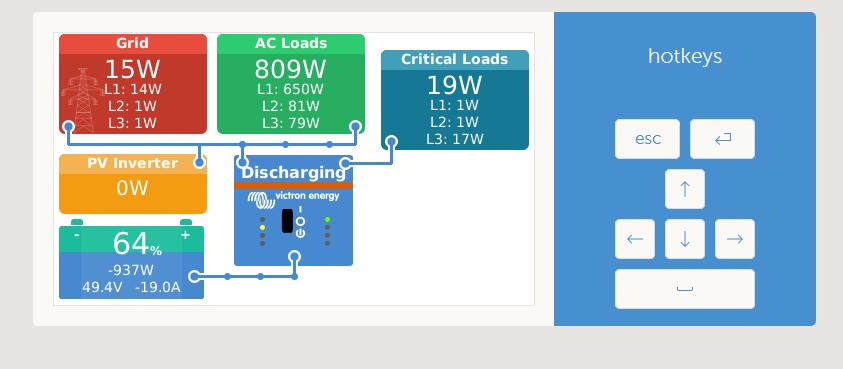
I run a 3-phase Multiplus-II installation set with one Multiplus II GX 3000 and two Multiplus II 3000. The PV is a set of AC/GRID-based Micro Inverters from Ae-conversion. The whole system works great with ESS and uses Pylontech as batteries. I am missing to see in VRM the PV output. I missed to install a AC Current sensor - # CSE000100000 for each phase. I know I need an additional assistant to run it with in the VE-Config to set up.

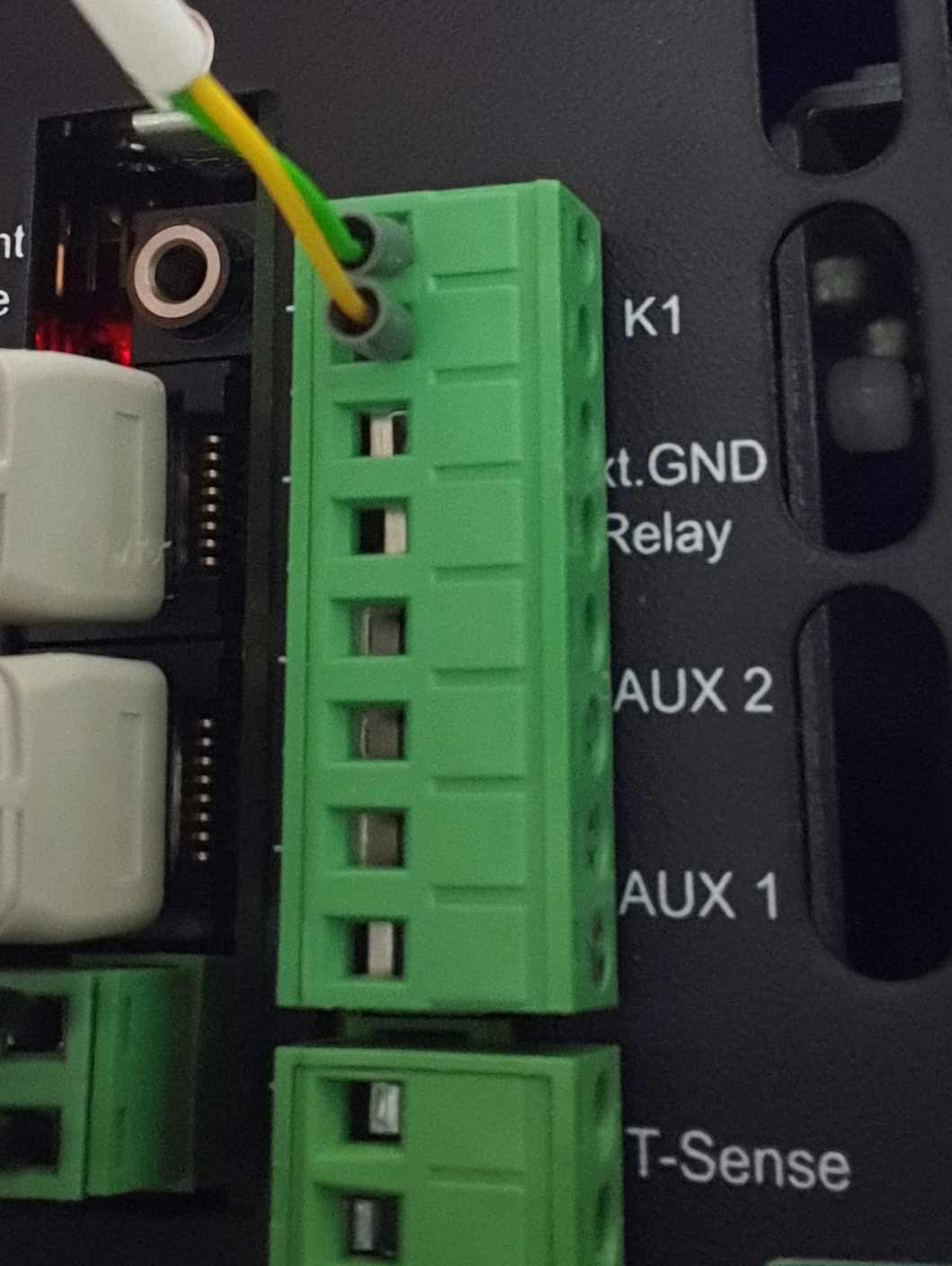
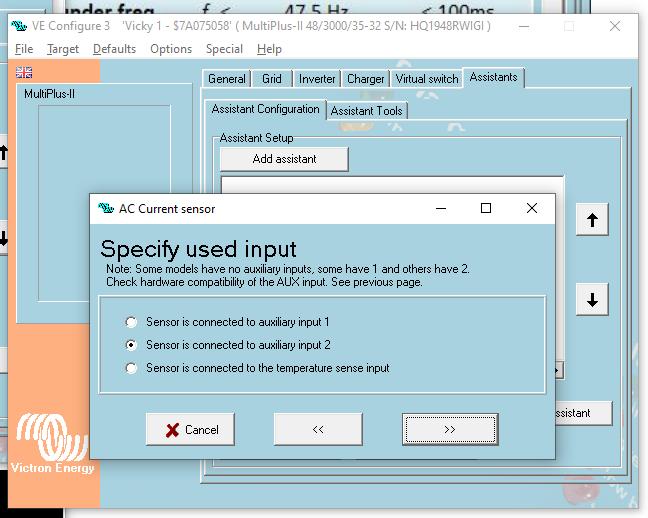
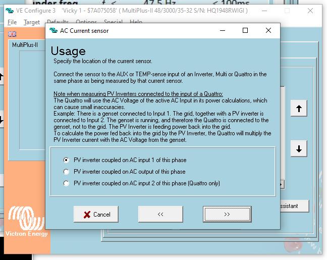
My plan: I wanted to measure each phase of the micro inverter set input to the grid with one of the above mentioned AC current sensors and connect it to the AUX Input 1 of the Multiplus-II/Multiplus-II GX corresponding for each phase.

By reading lots of documents and threads here I am at the end some how confused and no longer 100% sure if it will work as desired and if I can arrive at the end to see in VRM how much the micro inverters create PV energy and serve it to the ESS system.

Can somebody please confirm, that the AC Current sensor - # CSE000100000 is correct fot what I wanted to do? Or help me out of my wrong thinking? ;-)

Thanks for your expertise and support

DayAndNight

Multiplus-II
2 |3000

Up to 8 attachments (including images) can be used with a maximum of 190.8 MiB each and 286.6 MiB total.

3 Answers
Daniël Boekel (Victron Energy Staff) avatar image
Daniël Boekel (Victron Energy Staff) answered ·
2 |3000

Up to 8 attachments (including images) can be used with a maximum of 190.8 MiB each and 286.6 MiB total.

dayandnight avatar image
dayandnight answered ·

Thanks and kind regards from Munich!


DayAndNight!

2 |3000

Up to 8 attachments (including images) can be used with a maximum of 190.8 MiB each and 286.6 MiB total.

dayandnight avatar image
dayandnight answered ·

Hello Vicronauts!

Meanwhile I have installed for 3-phase Grid-connected PV inverters from AE-Conversion the above discussed AC-sensors CSE000100000 to my Multiplus-II ESS-system. I wanted to share my experience and some informations and facts what I found out during the installation and setup process. Perhaps it will be helpfully for somebody else.

I couldn't find anywhere the dimensions of this AC-sensor. They are about 90 x 60 x 60 mm (L x W x D). I needed this in the beginning for thinking where and how to fix them. Finally I decided to use a polycarbonate box I knew already from mounting the megafuses.

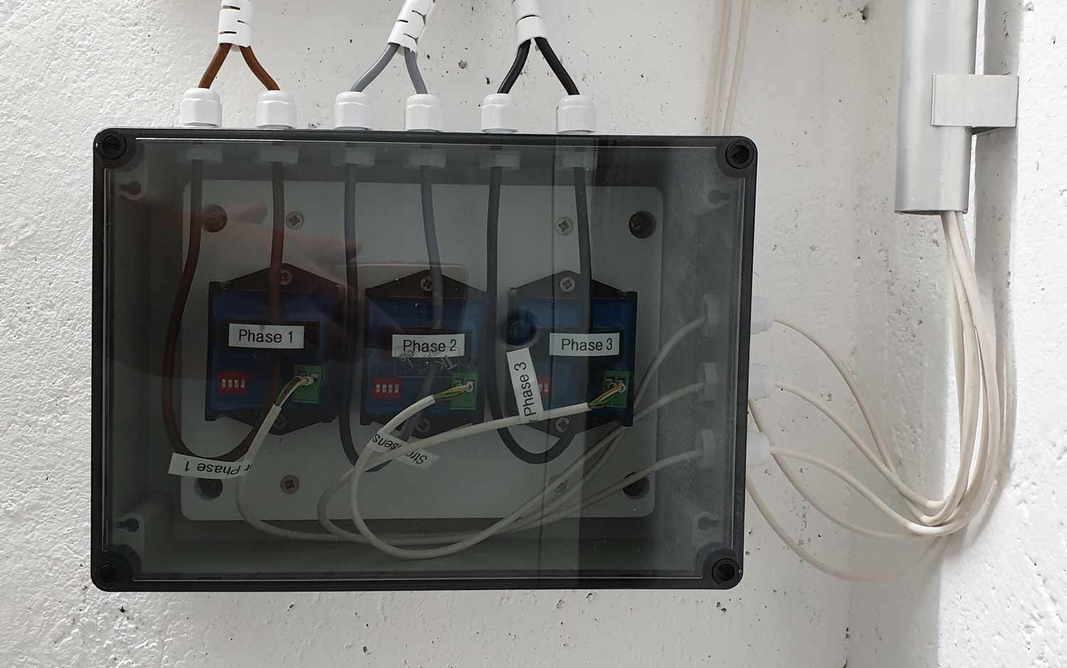
Those boxes aren't very expensive, but very stable and it is easy to drill holes for cables. For the AC-sensors there is no need for a transparent cover but I like to have some view to my equipment, so this was reason enough to use a transparent cover.
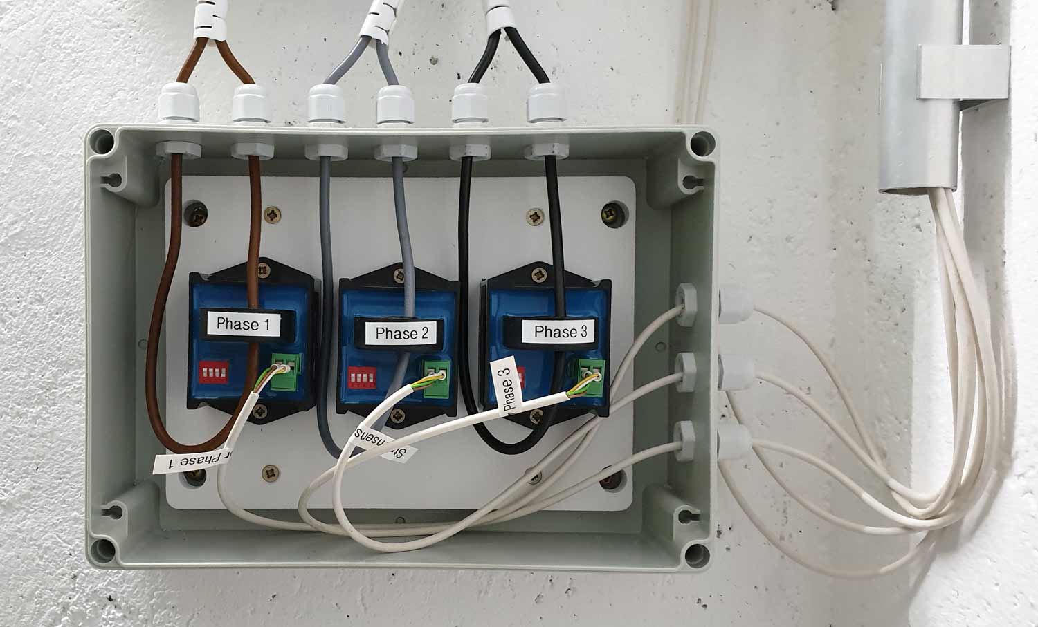
I mounted this box directly below my distribution box so it was not very complicated to get the three phase wires of the PV system and pass them thru the ac-sensors and back to the distribution box. You shouldn't forget to set the DIP-switches on the AC-sensor to the right power level of each single phase of your PV-system.

Wiring sensor cables! AUX1 or AUX2?

The output sensor cables I connected first to the AUX 1 Input port each of the three sensors to the corresponding Multiplus-II and thought this was a good idea.

But as AUX1 is blocked and can be used in Germany for a GRID-based Feed-In signal from the Grid-provider it blocks later discharging ESS when AC-sensors are connected to AUX1. Located in Germany, it happend exactly to me and I found with some research the explanation and solution in Q&A - Q9 - fourthly of the ESS documentation:

"... Fourthly, feed-in may be disabled when a grid code (like the German or Australian grid code) uses the aux1 input to disable feed-in, and aux1-in is used by something else (like an AC-sensor or a BMS), this way feed-in can be disabled. Simply un-check the option in the grid-code settings to prevent this."

But it isn't so easy as described in Q&A -Q9 just to un-check the option, because you need for doing this the GRID-Password or you reopen the Multipuls covers and rewire them all to AUX 2

After doing the wiring it is necessary to install the AC-Current assistant.


VE-Config AC Current Sensor

Here the screenshots of this assistant.

Keep in mind what is mentioned here at: Reactive current correction - it showed me the first night after installing the sensors that this PV system is working with moonlight, too ... ;-) but after 24 hours this effect was gone. Exactly as described here above.


As I said above, specially in Germany it is better to use AUX-2.


Of course you should select in the following screen the corresponding setting as you did with the DIP-switches at the sensors.


In this system the PV inverters are connected directly to the grid which is wired to AC input 1.


And don't forget in a 3-phase system you have to install the assistant with ve-config for each of the three Multiplus-II.

That's it! When you look the next time to your remote console you will find the yellow square for the PV Inverter

and as well in VRM portal the data of your PV inverters


I wish success and fun with your Victron ESS system.

DayAndNight


ac-sensor-02.jpg (90.5 KiB)
ac-sensor-01.jpg (97.5 KiB)
ac-sensor-03.jpg (73.1 KiB)
ac-sensor-04.jpg (51.5 KiB)
ac-sensor-05.jpg (68.6 KiB)
ac-sensor-06.jpg (51.2 KiB)
ac-sensor-07.jpg (54.2 KiB)
ac-sensor-08.jpg (62.4 KiB)
ac-sensor-09.jpg (30.4 KiB)
ac-sensor-10.jpg (52.5 KiB)
2 |3000

Up to 8 attachments (including images) can be used with a maximum of 190.8 MiB each and 286.6 MiB total.

Related Resources

Additional resources still need to be added for this topic