Hello
is there a way to connect temperature sensor to the raspeberrypi-venus and have the value display on the VRM portal... or other?
Hello
is there a way to connect temperature sensor to the raspeberrypi-venus and have the value display on the VRM portal... or other?
I can't remember if I got this working or not, there is some fiddling about to do and I vaguely remember using some sort of ADC as a front end for the temperature sensors.
I'll move this to modifications section, maybe someone else over there has better information than I.
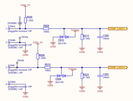
The ADC for the Pi supports three tank senders and 2 temp sensors as I believe the driver was taken from the Venus GX. So you could wire them up to the ADC, but it requires modifications to work with the venus. Check out my thread on tank senders and you can look at the schematic for the Venus GX to find the required resistors to get the temp sensor input working:
https://community.victronenergy.com/questions/19608/raspberry-pi-analog-inputs-tank-input.html
You can look at the Venus GX hardware BBB cape here:
https://github.com/victronenergy/venus/wiki/Venus-GX-hw-changelog
However with the Release of the Cerbo GX, that has 4 tank and 4 temp, so maybe we can use all 8 ADC ports in the coming months after the release of the Cerbo.
Although I had the tank sensors up and running in no time, the temperature sensors appear more problematic for some reason. I can see a voltage on the sensor setup page in the Venus menu but I am not succeeding in actually displaying a temperature. For the tank sensors I omitted the V clamp with the BAT54S and for the temperature sensor I woud like to omit the BAV99 (although I did try with an alternative circuit consisting of 2x 1N4148 diodes) The temperature sensors are the last of the inputs I would like to activate so if anyone can post a 'how-to'.......thanks
Jeroen
I followed the circuit exactly when I made the analogue input for my Rasberry pi and it worked pretty much straight away, I know you have seen my notes on my project. On the Rasberry pi you need the dbus-adc service installed but it sounds like you have that already if you see a voltage in the Venus menu and its easy to install on 2.60 anyway.
My notes on dbus-adc on Venus OS 2.60 are in this article here. You do need to create the dbus-adc.conf file in 2.60.
I am happy to help but I’m not sure what the problem is you are seeing? I’m using a system with 1.8 v Vref and can tell you the voltages I am seeing in the Venus settings and on the adc inputs if that would help.
Mystery solved!
Well, sort of.... All 5 LM335AZ I got did not work. I then drove to the van to piclup the temperature sensor that came with the Multiplus and connected that: Instant success. Now I need to source another couple of LM335's. Any known good/working brands?
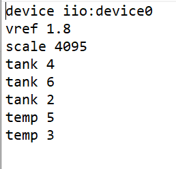
With regards to the dbus-adc.conf
Mine now looks like this (since the temp was not working I though to trey something else ;-))
device iio:device0 |
The custom names I assigned earlier are linked to the port, so '3' was labelled 'Fresh Water' but now appeared as a fresh water temperature sensor. All eight are configurable. The name determines their function, the number the port on the ADC chip......
Jeroen,
Glad you got it sorted I was going to invoke Ockham's razor and suggest that while both are quite unlikely, the simplest of the two explanations would be that rather than getting 5 dud parts, it might be a question of understanding the pinout of the LM335 especially in a TO-92 package, are you sure that at some point you did not damage the parts by wrong connection?
Anyway for reference here are some figures for you:
At 16 Deg C my LM335 voltage at the input to the circuit is 2.91 V and this is exactly the voltage reported on the Venus OS setup menu for the device.
The input voltage to the MC3208 is 0.92 which allowing for component tolerances is pretty much =2.91*4.7/14.7 which is what you expect from the voltage divider chain in the circuit.
I have an offset of -1 on the device to get it to report 16 degrees for this input level as I have calibrated my sensors by comparison with an i2c temperature probe which is also connected. The slope I have is the default (=1) and this give me reasonable accuracy from 0 C to around 80 C.
I don't know where in the world you are, I am in the UK and source all my parts from Farnell or RS ( formerly Radio Spares). I have never had any problem with component quality.
I got mine working with just the 3 resistors, LM335 & cap. But I got some odd temp readings and had to fiddle with scale and offset values to get sensible measurements. I was flying blind as there’s no explanation on what these actually do (that I can find). Eventually I got fridge and freezer within a few degrees of actual - close enough for my purpose.
Phil
Can you perhaps post a picture/photo/diagram on how you had it to work? I tried pretty much every variation I could imagine on the cape schema posted above by @nebulight.
Hi JeroenD
Here is how I wired mine...
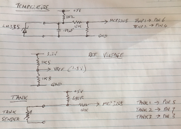
(Sorry about the crappy sketch).
I am in the process of installing the system in my caravan and it's currently dismantled so can't do any screenshots at the moment.
Phil
Just noticed my dbus-adc.conf file is slightly different to LaurenceH's ...

(Not sure it that's significant). Be sure there's a line-feed after 'temp 3' - caught me out.
I just rebuilt my system today (after somehow corrupting it during an upgrade to v2.60) and got caught out with an old version of the MCP3208 overlay. Apparently there was a new one around about November 2019. Once I loaded that one, everything worked. Prior to that I couldn’t get any analog inputs. But it sounds like your tank inputs are working so that is unlikely to be the cause for you.