Isolation Transformer 3600W
Has anyone else had this problem
would be nice if I could get a full circuit diagram
but to my understanding there should be no electrical path between Boat PE and shore
Isolation Transformer 3600W
Has anyone else had this problem
would be nice if I could get a full circuit diagram
but to my understanding there should be no electrical path between Boat PE and shore
Are you measuring between shore and boat? or the isolation transformer itself?
measuring between shore and boat you do on voltmeter position, not resistance.
Try unplugging shore-power, resistance or voltage should remain the same.
Hi Daniel
Could you possibility of sending me a circuit diagram
I had a Volt reading of 0.018V AC across the two earths
My I add that when unplugged from the shore line it reads open circuit
Any help is most welcome
Hi @Neil JB
So where did you measure this time? especially with shore-power unplugged?
there should be a reading with shore-power unplugged, between the shore-power earth and the boat's earth, either voltage (expected) or at least a resistance.
If not: please get an electrician involved to check your wiring / shore-power wiring.
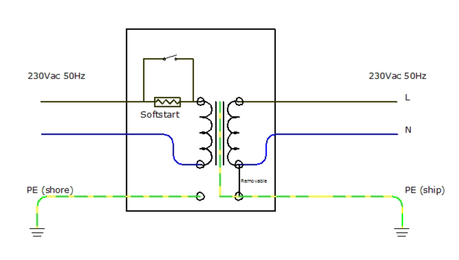
a diagram you can see here:
https://www.victronenergy.com/upload/documents/Datasheet-Isolation-Transformers-EN.pdf
I know the basics of a transformer . what I need is the circuit diagram of the control board
question
before I removed the transformer I had a residence of 128 ohms .. removed the transformer and set it on its side sill wired up
when shore line was plugged in there was no residents reading .. could it be a short on the transformer on the neutral side..i did do a 1000v merger test on winding to winding and to earth but all okay ...
I'm running out of idea's to where the fault is
at the diagram above, are you measuring from the left PE to the right PE?
if not, where are you measuring?
What version of the transformer do you have? I don't think the normal version has a relay.
but...did you measure the resistance on the transformer with everything disconnected? can you make a picture of where you are measuring?
If you measure with shore supply connected, your actually measuring the resistance between the shore PE and the hull of the boat...
unless its been jumpered (e.g. for when boat is on the dry) the two earths should not be connected. But if its been jumpered the resistance should be a lot lower than 100 ohms.
