I have a new version Multiplus 48/5000/70 connected to the grid with 260 Ah 48V battery back-up. Works perfectly. I would like to add 3kW of solar feeding into a seperate MPPT, a Multigrid 48/3000/35 with own batteries and connect on the 230V grid side of the installation, i.e. 2 independant parallel systems. Is it possible, and why not.
asked
Parallel operation of Multigrid and Multiplus, with both connected to AC input
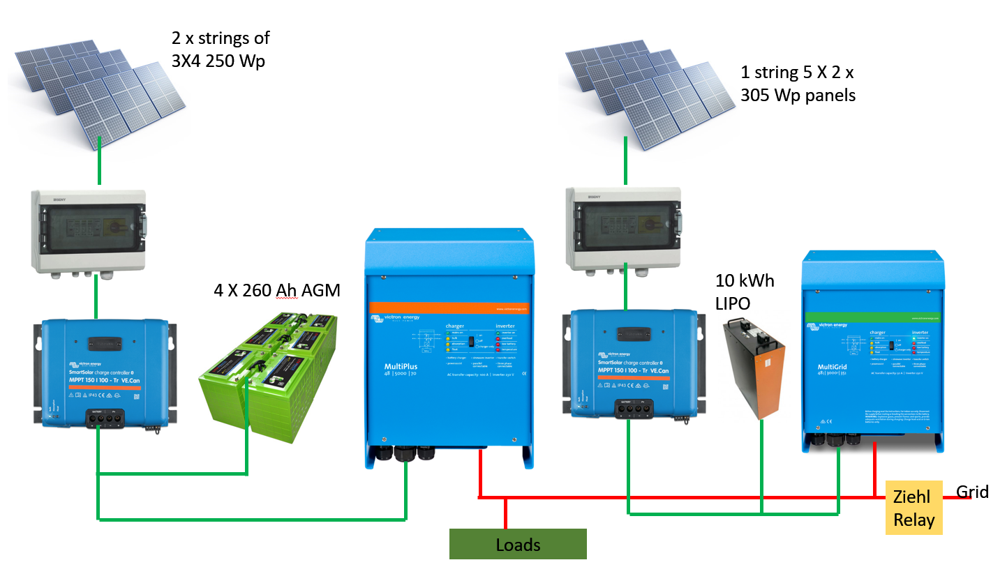 Please see attached.
the green lines going into the MP on the left hand side looks like they're going into the AC (the 3 grommets for AC in/outs). The red lines going into the right is where chassis slot on the units are for the DC terminals?
It looks like the lines got flipped
Yes, that was only by way of illustration - I am aware that it should be other way around.
From your description, it sounds fine. But please draw a diagram of the connections and post it, to be sure.
You could parallel the input side, but it would probably not be safe to parallel on the output side.
If you lost the grid input they could/would lose synch with each other.
I run something similar, but just using a single battery bank.
If I parallel the input side, how would the input from the solar panels behave with sharing the input between the 2 units? Or am I missing something?
And the batteries are then also in parallel?
The synchronisation between the units should not be a problem as it would be in sync if you loose the grid, and it should stay like that.
If you parallel on the input side with two separate batteries, they would be independent system, just like if had a system and so did your neighbor.
Your batteries also would not be in parallel using the same logic.
On the output side they would be in synch while you had the grid, they wouldn't will stay in synch if you lost the grid though. (They may not be equal voltages, even when in synch with the grid).
They shouldn't be paralleled on their outputs.
Now I am uncertain what is refer to as input and output - input being solar panels, output equals grid. The diagram above correct or not, should I connect all green together and split red?
Yes, with a bi-directional device that is capable of both importing and exporting both DC and AC power it is confusing.
I think the manual is consistent, it refers to "AC in" ( grid connection), with AC1 out and AC2 out going to loads. I am using the same convention.
From your drawing, I interpret you are mixing up hybrid inverters with PV grid-tie inverters.
A PV grid-tie inverter only has one AC connection as you've shown.
I'm thinking about Guy's response on the one hand, and the following thread on the other:
https://community.victronenergy.com/questions/22789/two-multiplus-in-parallel.html
There's the AC in and AC out on the units.
Paralleling on the AC in looks like two units in adjacent dwellings. And when power is pushed back out into the grid, synchronisation and all that is handled as per design.
Paralleling on the AC out is where you run into problems I'm thinking - the units need to be configured as a parallel assembly to work.
The diagram as drawn doesn't differentiate between the two.
Edit: oops this is what Phil was saying.... which is different to thinking about the DC as input and the AC in/out as some kind of a merged output.