Can I use Venus' built-in relay to control 5A 12V blower?
asked
Venus GX relay to control a 5A 12V blower
No, I think that is to much for the relay of the Venus.
But you can use the Venus relay to control a stronger relay that can drive the blower.
Thank you for your opinion, which is similar to mine. As I prefer to keep a circuit as simple as possible, I need the answer based on the data. In the Venus' datasheet, there is a limit of 6A 30VDC. I'm not an electrician, but I know that different types of loads have different properties and I want to be sure.
like matthias lange said, better use a power relay to protect your venus relay
dont forget to put a diode over the power relay coil to protect the venus relay contact
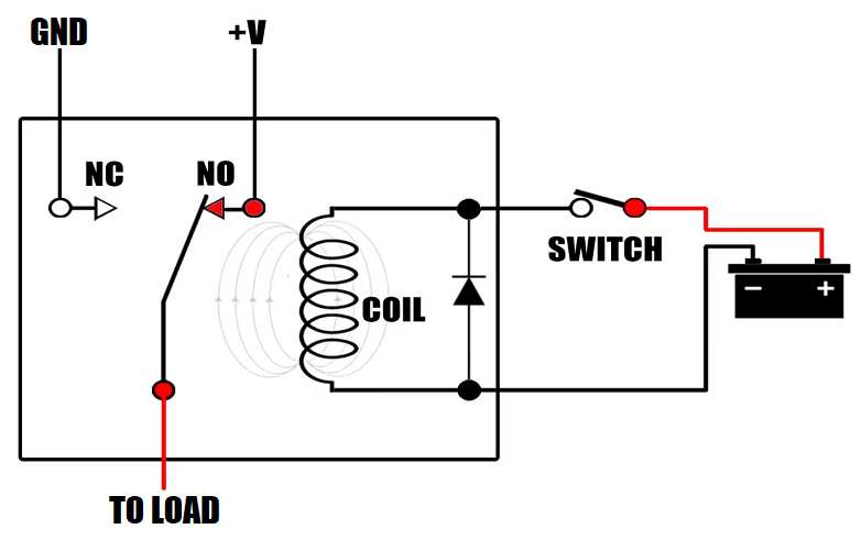
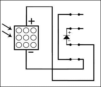
Just a clarification on your drawing. I have seen many contrasting drawings. In yours, you have the diode across the negative and positive wires.
According to some sources, with such a connection, the diode only serves as a "bypass" diode, not a "blocking" diode. Such sources say that for a blocking diode function, one has to connect the diode along the powered line (positive only).
Or is it the other way round? I'm confused.
F.
It's correct how the diode is placed and its "polarity", but this diode snubber type is used to protect the silicon junctions that drives the relay coil from reverse currents, which are killers for transistors junctions.
For protecting (relay) contacts, which don't care about the sense of the current, generally, an RC type snubber is used, across the switch / relay contacts.
Or to accommodate both, use an RCD snubber. Which might be overkill... :-)))
@Alex Pescaru
Clear. I'm assuming that the logic is the same when using an external solid state relay or any other type?
F.
Hi @Suavek
While the datasheet values are in range for your application, switching 60W through a small relay will not provide a long life for that relay.
The problem is the DC arcing, that is bigger and bigger as the load increases.
Successive arcing during time will lead to a slow destruction of the relay contacts and sooner than later the contact will either melt or fuse together.
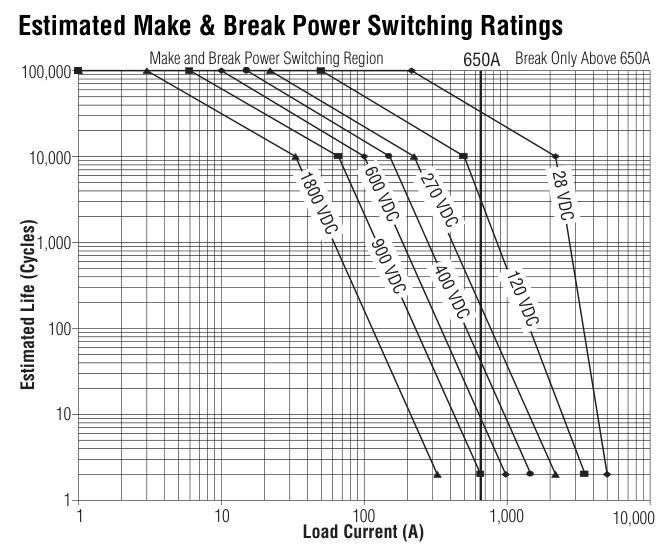
Here's below a graph for seeing the cycle life of a high power DC contactor from Tyco.
You can clearly see, the greater the current (power), the less switching cycles.
So, if you want to protect something that's inside and difficult to replace, switch an external relay which is easier to replace.
Alex
@Alex Pescaru and @Duivert NL, sorry to come back to you and for hijacking this thread but I think the OP will find this information useful.
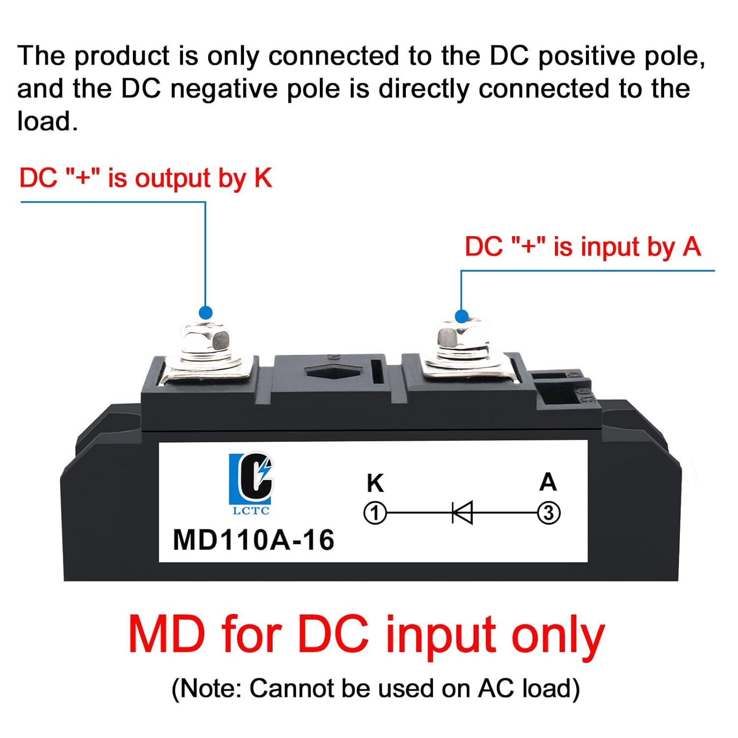
Looking at the Amazon US site again, all the listed manufacturers say that their diodes should only be connected inline the positive side only (see attached photos). My tentative conclusion is that the wiring depends on the manufacturer. I searched for "schottky diode" and for "blocking diode". It seems Americans don't use the term "snubber".
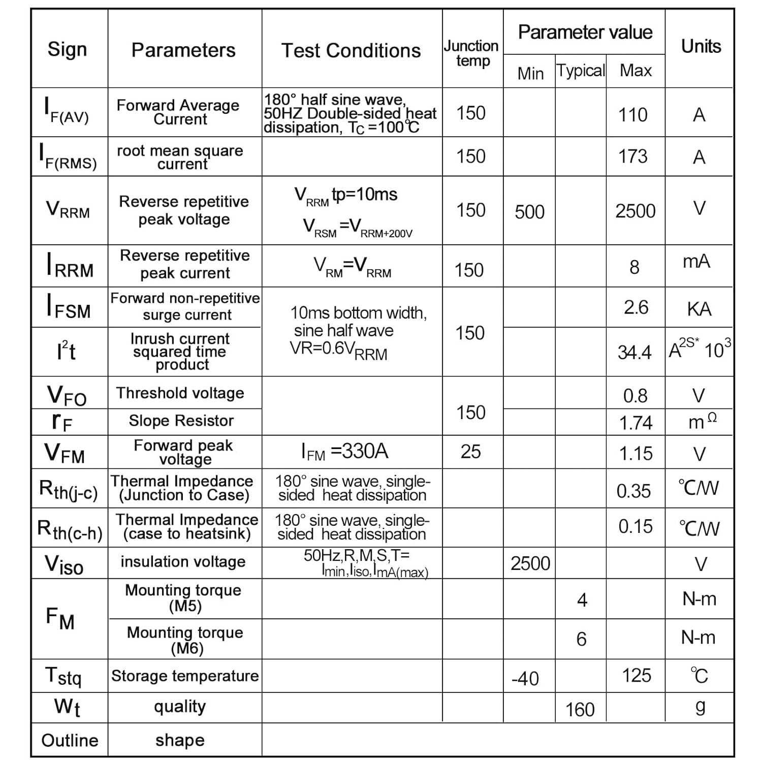
Second question: which specific one would you pick? It seems the MD is an overkill. Its specs and link below. The second one has less capacity but it is cheaper. Link also attached.
1. MD
2. Generic
Hi @Fideri
I believe that you / we are talking of different things.
Those diodes you are talking about are for combining / isolating DC sources or bypassing PV panel elements when shading occurs.
They are high power/current diodes, not like those used for induction protection.
Like these from victron: https://www.victronenergy.com/battery-isolators-and-combiners/argo-diode-battery-combiners
Alex
We might be talking about different types. But according to their documentation, those quoted serve to prevent "reverse currents" and protect "junctions"from such power. They are not bypass diodes.
F.
Yes, they are... :-)))
In the end, a diode is a diode. Conducts electricity only on one direction and is used to protect devices, in our both cases, but for different purposes.
Only that in one case is a small current diode, in the other is a high current diode.
Diodes are like one way valves in pipes, if the voltage on the + side of the diode is higher than the voltage on the - side then current flows in the direction of the arrow. If the voltages are reversed then no current flows. You understand diodes.
If the snubber / back emf diode on the relay, normally it does not let any current through because the +12V is connected to the diode negative. However, when the switch (Cerbo relay) is opened, the magnetic field in the power relay collapses and generates a reverse voltage (back emf). This voltage can be very high, damaging the switch. The diode conducts the current resulting from the back emf because the back emf makes the positive output of the relay go negative. As the current passes through the diode, this stops the voltage over the switch getting too hogh so that the switch is not damaged.
Hi @pwfarnell
You are right, but it seems that I am failing to make him understand between two different cases: when the diode is used as a snubber / back emf or when it's used as a bypass diode...
Read his message 6 hours ago in response to Duivert. Quote below....
According to some sources, with such a connection, the diode only serves as a "bypass" diode, not a "blocking" diode. Such sources say that for a blocking diode function, one has to connect the diode along the powered line (positive only). Or is it the other way round? I'm confused.
Maybe you can make him understand better than me...
Alex
I think I understand the aim here perfectly. We are aiming to protect the Cerbo relay from the reverse power generated in the external relay. For that we use a "blocking" diode to halt any stray power from passing through to the Cerbo relay. I'm I correct in this?
The question then becomes what relay to use and how to wire it. According to a description of one of the two relays I quoted: "This model is anti-reverse diode MD 110A-16; to prevent backfeed ;Also called blocking diode". The said diode is "Schottky" diode. According to the instructions, it must be installed inline with the positive wire (not across on positive and negative wires). Is this the wrong kind of doide (I believe it is too big but serves the function)? Is the wiring wrong?
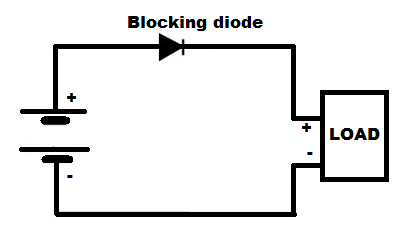
As I mentioned, according to some sources, the same diode can be used as a "bypass" or a "blocking" diode. It is however wired differently. A "bypass" diode goes across the positive and negative lines but a "blocking" diode goes along the positive line only.
Here is an example drawing from basic circuits. Where there is "load", I would put the external relay.
Fideri
The diode in this configuration will only allow the current to flow in one direction.
During the circuit opening, there are voltage spikes generated by the inductor (relay's windings). These spikes travel all around the circuit loop.
You need to "consume" these energy spikes when the circuit opens, not allow them to flow in one direction.
For "consumption", you need to put the diode in parallel with the inductor, or when this is not possible, you need to suppress the spikes with an RC snubber in parallel with the protected element (switch).
If you put a diode like that between the switch and the relay it does not stip the high voltage back emf from being generated even if it stops the reverse current flowing to the switch. Putting the reverse polarity diode parallel to the relay means and back emf voltage is limited to 0.5-0.7V depending on the diode type and the power is dissipated in the diode / relay coil.
That's clearer. To be on the cautious side, I will buy 2 diodes and wire one in parallel and the other in series, if it has no negative effect. I know one of the diodes will be redundant but that is fine by me.
F.