question

ee21 avatar image
ee21 asked

Need some help defining "Frequencies" in ESS for SolarEdge PV inverter

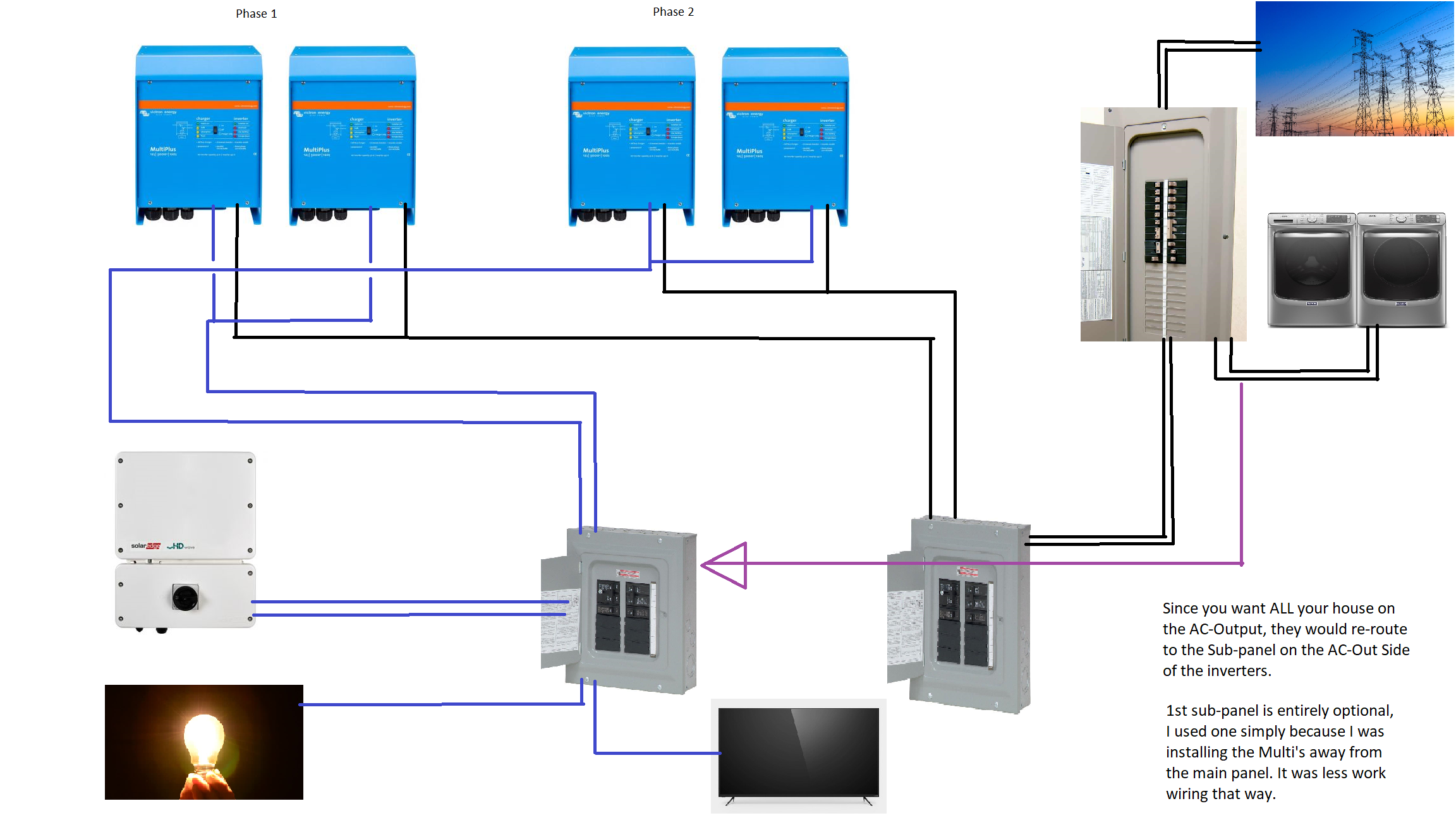
I could use some help defining the disconnect frequencies in ESS for my PV inverter shown here; any help is appreciated!:

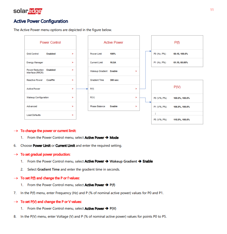
I live in the US, my inverter is 60Hz first off, these are default values I have not modified yet. My Inverter is a SolarEdge HD10000-H US. Active Power control via frequency is defined here in the manual, and can be set by the user:


It would seem that "P0 in my inverter relates to "The solar converter will start reducing its output power at XX Hz", I am guessing that P1 would be the next setting "Output power will be reduced to minimum when frequency is at XX Hz".. I am not sure what to enter for the final disconnect value though. The full manual on Power Control can be found here, https://www.solaredge.com/sites/default/files/application_note_power_control_configuration.pdf


Can anyone provide any recommendation as to how I should configure this in ESS and which values should be selected for P0 and P1 in my inverter?

ESSfrequencysolaredge
screenshot-18.png (6.4 KiB)
screenshot-20.png (117.8 KiB)
2 |3000

Up to 8 attachments (including images) can be used with a maximum of 190.8 MiB each and 286.6 MiB total.

3 Answers
ee21 avatar image
ee21 answered ·

Despite a lack of support from both SolarEdge and my installer on this matter, I managed to get this working after some testing.


Step 1: Access the Settings menu of the inverter, by holding down the OK button for 5 seconds. Enter the password (default is UpDownOkUpDownOkUpDown)

Step 2: Enable Energy Manager if power controls not already available

https://www.solaredge.com/sites/default/files/application_note_power_control_configuration.pdf

Step 3: Set Power Frequency control P(f) via the instructions in the link above. Set P0 to 60.1HZ,100% or 50.1Hz,100% depending on your location.

Step 4: Set the frequency used for P0 in the last step in the ESS assistant, use that value for "The solar converter will start reducing its output power at XX Hz"

Step 5: Set Set P1 to 62.1HZ,0% or 52.1Hz,0% depending on your location.

Step 6: Set the value used for P1 in ESS Assistant for "The inverter will disconnect when frequency is higher than"

Step 7: Set "Output power will be reduced to minimum when frequency is at XX Hz" 0.3 Hz lower than the value used for P1


I successfully tested and have my HDWave 10000 working on the AC Output of my Victron. By the time AC frequency reached 60.2Hz the output was sufficiently reduced so that my batteries did not overcharge.


You may not be able to adjust P0 or P1 in the inverter, that is okay. Just read whatever the defaults are and use that in ESS Assistant


My inverter will enter "islanding protection" when the grid fails using LOM Type B, but will reboot after 5 minutes and start outputting power to the Victron micro-grid

4 comments
2 |3000

Up to 8 attachments (including images) can be used with a maximum of 190.8 MiB each and 286.6 MiB total.

charl-ccu avatar image charl-ccu commented ·

Hi, thank you so much for sharing this solution.

I suppose you are allowed grid feed-in? I would've liked to get a Victron inverter to implement with my SolarEdge grid-tie system but my grid meter trips if it detects even the tiniest amount of current reversal.

0 Likes 0 ·
ee21 avatar image ee21 charl-ccu commented ·

Oh, yes definitely, we have obtained an interconnection agreement and I think a meter upgrade from the utility company as part of the solar install.

0 Likes 0 ·
phitur avatar image phitur commented ·

@ee21, is it possible to provide a diagram of your setup? I am interested in doing something similar and am about to install a system with two 10KW SolarEdge HD inverters. I'm getting it setup to allow for adding the VE Quattro 10K later to allow for AC coupling and islanding of my house.

I ran across a statement on this page, "it is possible for the SolarEdge to be used in ESS systems where feed-in to the grid is allowed, but only when connecting the SolarEdge to the AC-input of the Victron inverter/charger." However, this page clearly shows the PV inverter on the AC-output of the Victron unit.

Until coming across the statement above, my assumption was the Victron Quattro would perform the disconnect function and the ESS would allow for islanding with PV production on loss of grid when designed as indicated in the drawing. My intent is to supply my entire house with 200A service using two 10K Quattros in parallel with 100A on each. Ultimately, I want to know if Victron has the right solution to do what I want and how it needs to be designed. I'm curious to know how your system is designed and with what components are used.

Thanks

0 Likes 0 ·
ee21 avatar image ee21 phitur commented ·

@Phitur I don't have CAD or any professional tools available, but I did the best I could with Microsoft paint haha.


What you are trying to accomplish should totally be doable with 2 10k Quattros, and VicronEnergy is the right product.. You would connect the PV inverter - along with the rest of the entire house - to the AC-Output of the Quattros... You will be looking at something very similar to my diagram, with the exception of ALL loads being connected to the sub-panel on the AC-Output side of the Quattros, instead of some large loads connected to the main panel like I do. My inverter setup is simply not enough to power my whole house when the grid goes down.


Victron does not officially support SolarEdge inverters, and as such, their use is very poorly documented, or supported by the community. As far as I know, I am the first person to get such equipment to run when connected to the AC-Output side of the Victron Inverter. That being said, I can verify it works, the latest SolarEdge inverters support all the required functionality to control them off-grid using Victron inverters. My original post documents how to accomplish this, which is done all via settings - no special wiring.


As far as wiring does go, since the main-panel is where the meter is, you cannot connect anything upstream from here - the Quattros themselves for example cannot be connect prior to the main panel. So, you will need to wire the AC-Input of the Quattros to the main panel using 100A breakers and some very thick wire. Following that, you will need to connect a sub-panel with a 200A rating, to the AC-Output of the Quattro. This sub-panel will in effect become your main panel. Everything, from AC loads to the PV inverter will connect here - or downstream from yet another sub panel.. Very simmilar to what I showed in my diagram. I would suggest, if deploying this before the Quattros are installed, that you simply wire a 200A Sub-Panel, straight to the main panel, then wire everything to that sub-panel as if it were powered by the AC-Out of the Quattro - when it comes time, then just drop the Quattro in between.


If you have any questions, you can email me, TDEnergySystems@gmail.com

Parts used:

4x MultiPlus Compact 2000

1x BMV-712

1x VenusGX

3x SquareD 6-Circuit LoadCenter

A lot of copper wire, blood, sweat and tears


0 Likes 0 ·
untitled.png (739.8 KiB)
stewer avatar image
stewer answered ·

@ee21

Hi, maybe your post is the answer to my problem / question:

I have a 9.7 kWp solar installation with a 3-phase Solar Edge inverter. I am now thinking about 1. adding a battery and 2. achieving blackout protection / island operation while the public grid is down. Solar and battery should power the island (as long as they can). It seems that maybe 3 x Multiplus II could be a solution for a 3-phase island operation in combination with the SE inverter (I am still not sure). My question: how is the Multiplus handling an island condition where the solar edge inverter provides more energy as battery and loads can consume.

From reading your post I think your are trying to handle the same condition and what you are describing is the answer on that, right?

Can you explain a bit more in detail “... "islanding protection" when the grid fails using LOM Type B, but will reboot after 5 minutes”
Thanks so much for an answer! Stefan

4 comments
2 |3000

Up to 8 attachments (including images) can be used with a maximum of 190.8 MiB each and 286.6 MiB total.

ee21 avatar image ee21 commented ·

You will need 1 MultiPlus per phase, so if 3 phase then 3 Multi's will be needed, that is correct. Please be aware of the Power Factor 1.0 Rule when sizing the inverters: https://www.victronenergy.com/live/ac_coupling:start


When operating off-grid, or without any AC-Input connected (when there is a power outage), the Victron inverters establish a micro-grid which allows the AC PV inverter to keep running. To control the power output of the PV inverter, e.g. when the AC loads are low, and the batteries are all full.. Frequency Shifting is used by the Victron Inverter, to scale down the PV inverter output. The instructions I posted above are, step by step, how to configure this feature using a SolarEdge PV inverter. Half of the work is done in the SolarEdge inverter menu, and the other half is done in the Victron Inverter configuration. Please be aware that configuring a multi-phase inverter installation, as well as AC-coupling a PV inverter are considered "advanced" installations, and Victron staff will advise you take a training class rather than providing you direct support in this matter. I am just one homeowner, I do not run any sort of business that specializes in this, nor do I have any professional qualifications. I merely have enough experience working with electricity, and enough luck I suppose, to work my way though all of this myself.


And lastly, when running on-grid using the Energy Storage Assistant (a plugin for the Victron Inverter, Google it to learn more), this requires you configure a method of what is known as Loss of Mains detection (LOM) (or Grid Down detection), these are the parameters with which the Victron Inverter checks against the AC Input; if the voltage goes out of bounds, or any other of the parameters are violated, which may indicate the grid has failed, the Victron inverter will cut the connection and enter "island" mode... Either due to the way I have this option configured, or due to the sensitivity of the Solar Edge inverter I am not sure which, this transition will trip the safety on my SolarEdge, which will cause it to shutdown for a moment, and then subsequently it takes 5 minutes to warm-up again, after which time it begins normal operation, in off-grid mode. This is not a problem really that I can see, in fact I kind of like this because it avoids any large spikes in power output. It just means you will be running off-grid on battery-only for about 5 minutes when the grid fails.


0 Likes 0 ·
stewer avatar image stewer ee21 commented ·

@ee21

Thanks a lot for your answers, this is very helpful, also the link! Here in Germany it is not so easy to get good information about gird-off solutions for grid-tied PV inverters, normal electricians are mostly not familiar with this kind of equipment, Victron is not common here, and the SolarEdge support is not responding for weeks now.
Maybe you also have knowledge about the following: Assuming I will install only one Mulit (for 1-phase). The grid is down (LOM), the Mulit establishes a 1-phase micro grid. So the SE inverter sees only 1-phase on and 2-phases off. Will the SE provide power on this one phase it will it comply shut down?

The Factor 1.0 rule appears easy to understand. However, what is not clear to me: the scenario described under “2.2 Example and background” seems to be generally valid, also if the “factor 1.0 rule” is met. In other words I cannot understand why meeting the “factor 1.0 rule” will generally protect against a possible voltage spike and its consequences. Any ideas?


Regarding LOM: I think I read somewhere that the Multi need 20 ms for switchover / establishing the micro grid, which is on one hand quite fast and severs for loads as UPS: On the other hand I would assume (I do not know this) that the SE inverter detects LOM in <20 ms and shuts down (goes into island protection).

0 Likes 0 ·
ee21 avatar image ee21 stewer commented ·

Nobody here in the United States has much, if any training with off-grid equipment installations either unfortunately. SolarEdge was completely unhelpful for me as well, and simply instructed me to contact my equipment installer.


If your SolarEdge is a 3-Phase inverter, it will need a 3-Phase micro-grid I'm afraid, I am 99.9% certain about that. You can test by disconnecting 2 of the 3 AC-Input phases from the Grid, and see if it will operate. Likely it will shutdown.


Regarding 2.2 in the PowerFactor 1.0 documentation, I am not 100% clear on this either, lacking any training from Victron on this myself. My understanding is this.. AC Loads are high - you are running a heater or something, AND the sun is high in the sky, PV inverter Output is at it's maximum - whatever that is... Now, your heater is turned off.. In that moment, the Victron Multiplus will use Frequency Shifting to tell the PV Inverter to lower its Output, but for a short moment before PV Inverter Output goes down, only milliseconds maybe, that extra energy has nowhere else to go. So the Victron Multiplus will dump it into the batteries using the DC Charger.. If you have a very large PV Inverter, but a very small Victron Inverter (not meeting the 1.0 Rule), in that very short moment, the very small Victron Inverter will not have enough DC Charging capacity to divert that "spike", so the AC Voltage goes up, bad things happen.. If you meet the 1.0 Rule, then the Victron Multiplus will be able to convert all of that "spike" into DC energy sent to the batteries instead. Even at 100% full, a 1 second pulse should not cause any issues with a good size battery.


And lastly, I really do not know why the SolarEdge shutdown on me, no other equipment does. In Germany, Victron has the proper certificates which allow you to set LOM Type A and B I believe, where in the USA here I only have Type B available to me. Perhaps Type A will yield better results for you, although as I mentioned a temporary 5 minute loss of Solar is not a big deal that I can see.

1 Like 1 ·
stewer avatar image stewer ee21 commented ·

Again, thanks a lot! Very well desrcibed.

0 Likes 0 ·
xury avatar image
xury answered ·

hi ee21. If I understand correctly, you are not using APS mode on your SE inverter? You only set P(f)?. And do not set sunspec ID 126 etc on modbus tcp? My only requirement is to reduce the power after the power grid goes out.

2 |3000

Up to 8 attachments (including images) can be used with a maximum of 190.8 MiB each and 286.6 MiB total.

Related Resources

What is ESS training video

ESS Quick Installation Guide

ESS design and installation manual

Additional resources still need to be added for this topic