question

carlosleon avatar image
carlosleon asked

How to get accurate SOC when charging the batteries with solar panels?

Hello everyone,

sorry if this subject has already being answear.

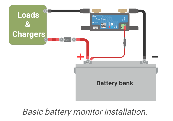
I have 5 Lithium batteries connect to positive and negative Bus Bars and from each Busbar there is one main wire that goes to the Multiplus, between the negative Busbar and the multiplus I have installed the Victron Battery shunt. So far so good, the battery discharges through the Negative Busbar across the battery SmartShunt and into the Multiplus, then I get a correct SOC reading, But I've installed and connected solar panels through and Victron MPPT that feed directly to the Positive and negative Busbar, in this case the battery shunt doesn't seen to know that while the batteries are being discharge there are being charge by the solar panels. So the Shunts only subtracts the amps that goes through and eventually show 0% SOC, in my case when 235 AmH have being use from the batteries.

Am I doing something wrong?

Thank you

SmartShunt
2 |3000

Up to 8 attachments (including images) can be used with a maximum of 190.8 MiB each and 286.6 MiB total.

3 Answers
chrichri avatar image
chrichri answered ·

Did you use a MPPT from Victron connected via VE.direct ?

If so, the calculation will be done without the necessity of a shunt.

2 |3000

Up to 8 attachments (including images) can be used with a maximum of 190.8 MiB each and 286.6 MiB total.

pwfarnell avatar image
pwfarnell answered ·

What you are doing wrong is connecting the negative wire from the MPPT to the bus bar, the MPPT negative must be connected to the load / system side of the shunt, all details on this are in the manual. Then when current flows from the MPPT to the batteries it flows though the shunt and can be counted.

screenshot-20240523-141312-kindlephoto-155146462.png


1 comment
2 |3000

Up to 8 attachments (including images) can be used with a maximum of 190.8 MiB each and 286.6 MiB total.

kevgermany avatar image kevgermany ♦♦ commented ·
The way I read the original post is that the busbar is between shunt and battery.

@chrichri if this is the case, the shunt must be between the battery and the negative busbar, otherwise your other negative connections will cause problems as well.


0 Likes 0 ·
Duivert NL avatar image
Duivert NL answered ·

Take a look at section 4.8 in the wiring unlimited manual about correct shunt placement and connection

https://www.victronenergy.com/upload/documents/The_Wiring_Unlimited_book/43562-Wiring_Unlimited-pdf-en.pdf

2 |3000

Up to 8 attachments (including images) can be used with a maximum of 190.8 MiB each and 286.6 MiB total.