question

brinx38 avatar image
brinx38 asked

How to “Reverse Charge” Tesla battery using SmartSolar MPPT 150/60 Tr

Hello everyone,


I’m trying to get a Victron engineer or someone familiar with their Charge controller design (and also lithium batteries) to tell us under what circumstances could any of their BlueSolar / SmartSolar controllers “reverse charge” a Lithium Battery.

Background on the question:

A couple months ago I ditched FLA and switched to a pair of Model S Lithium batteries in series for 48 Volts.
I also put in a new charge controller 150/60 and BMV-712 as I thought the Victrons had the best product line for managing and protecting a Lithium installation.


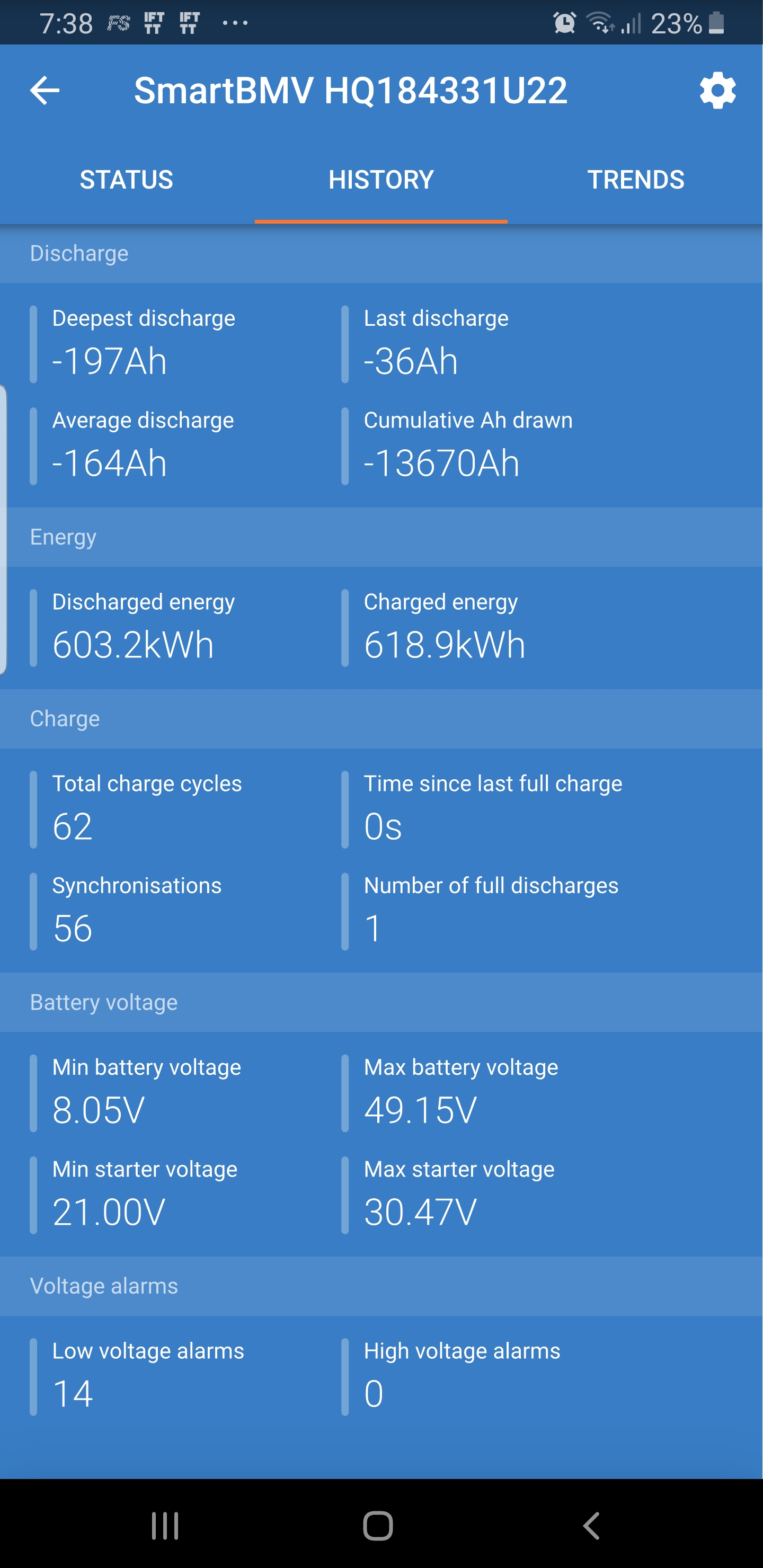
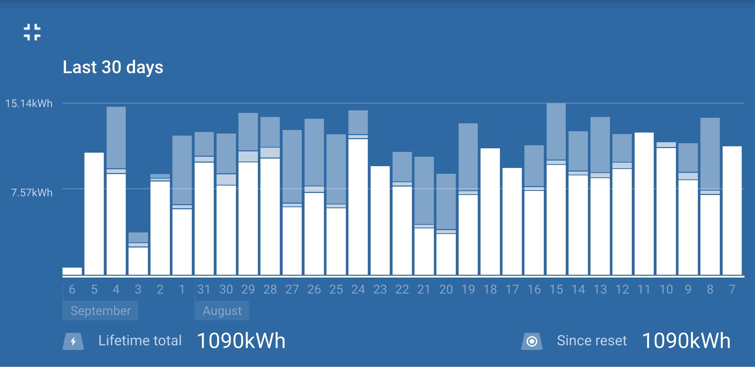
As can be seen from the two charts above, this has been working flawlessly for over 60 days.


I have been noticing that prior to sunrise, my Tesla modules may get down to 20% SOC or about 39 Volts because I have the Victron stuff setup like so.


Wanting to prolong the lifespan of these two Tesla modules (by not cycling them so deeply every day), I thought I would add another pair in parallel and double storage capacity in one go.


So, I bought another pair of 5.3KWh modules (with warranty), but thought it would be a good idea to run this new pair by itself for a few days before I put them in parallel with the already working set.

Modules arrived pretty well balanced at ~20 Volts each, and within 0.2Volts of each other. So, so far so good.

I used two of the M8 terminal bolts from my existing two modules (because one of the modules arrived without terminal bolts) and also used the existing 1/0 cable from the working modules to connect the (+) and (–) terminals together in series for 48V,
and swapped in the new modules in the place of the old modules.


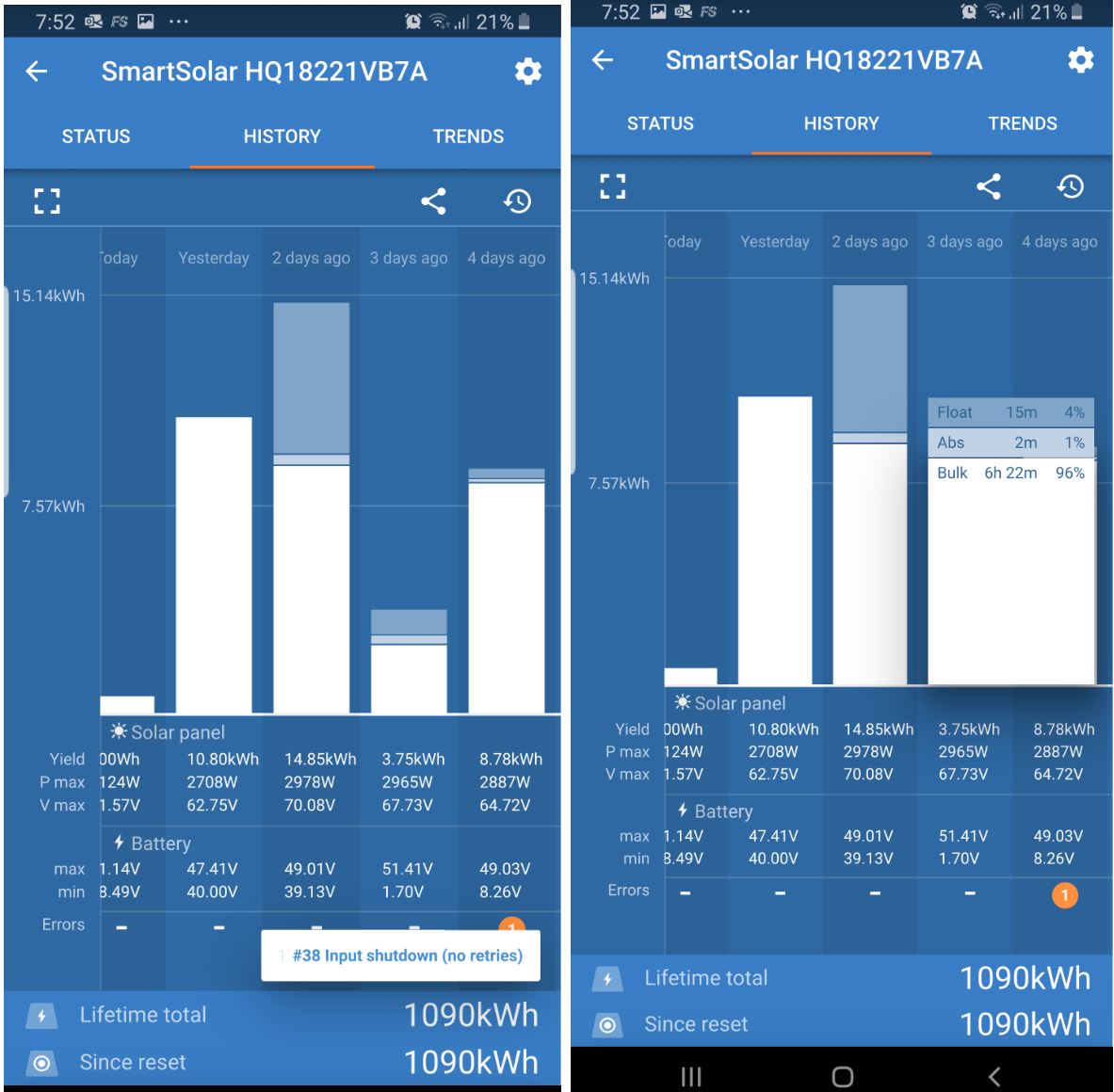
As can be seen from Bar Chart above, (under the 4 days ago column), the battery conked out after 15 minutes in float. With Error #38.

After disconnecting the modules and looking into this further, I realized that one of the Tesla Modules was at 19+ Volts, while the other was at 25+ volts.


Upon contacting the battery vendor telling him that one of the modules is DOA, he said “when
you charge them and are charging 2 together in line at the same time, the
first battery charges first then the second one starts to charge. Thats
how they work. If you swap the order of the batteries you will see other
battery charges first then second” - over a decade experience working on High Voltage and commercial UPS installations and I must admit I have never heard any such thing before.


Anyway, vendor suggested that I do load tests to see which battery depletes faster.

With one DC water heating element and within 30 seconds I identified that the module that came without the bolts would voltage sag while the other module did so negligibly.

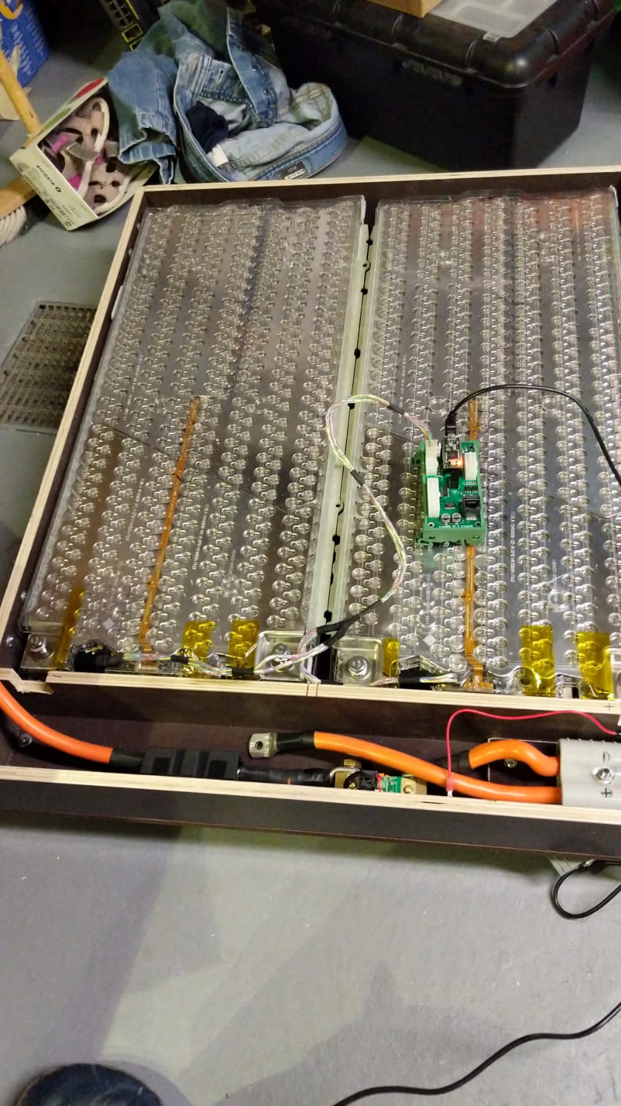
Battery vendor then says that these test result are irrelevant so I suggested we check the individual voltages that make up the 6S.

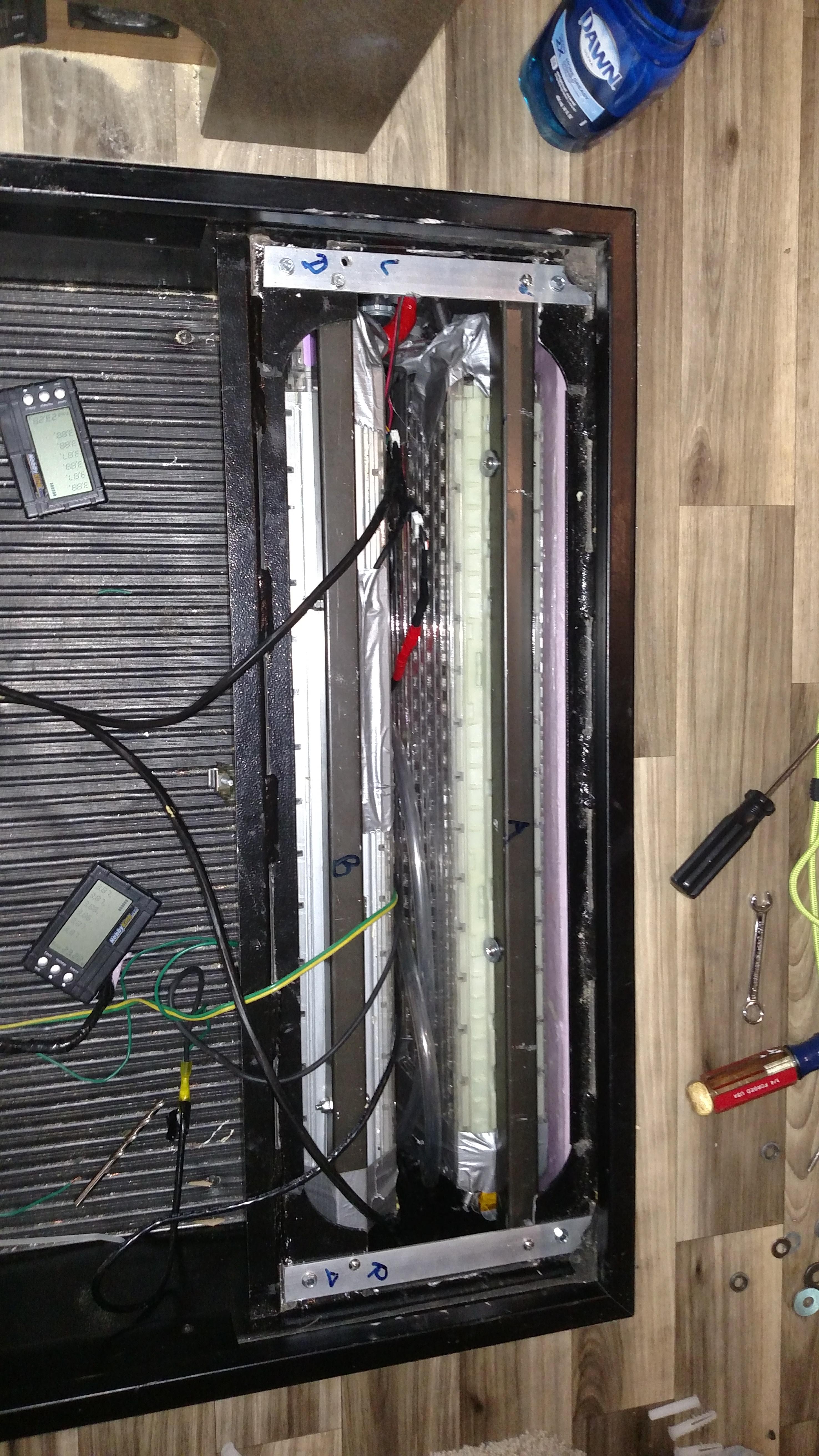
This is what I found.


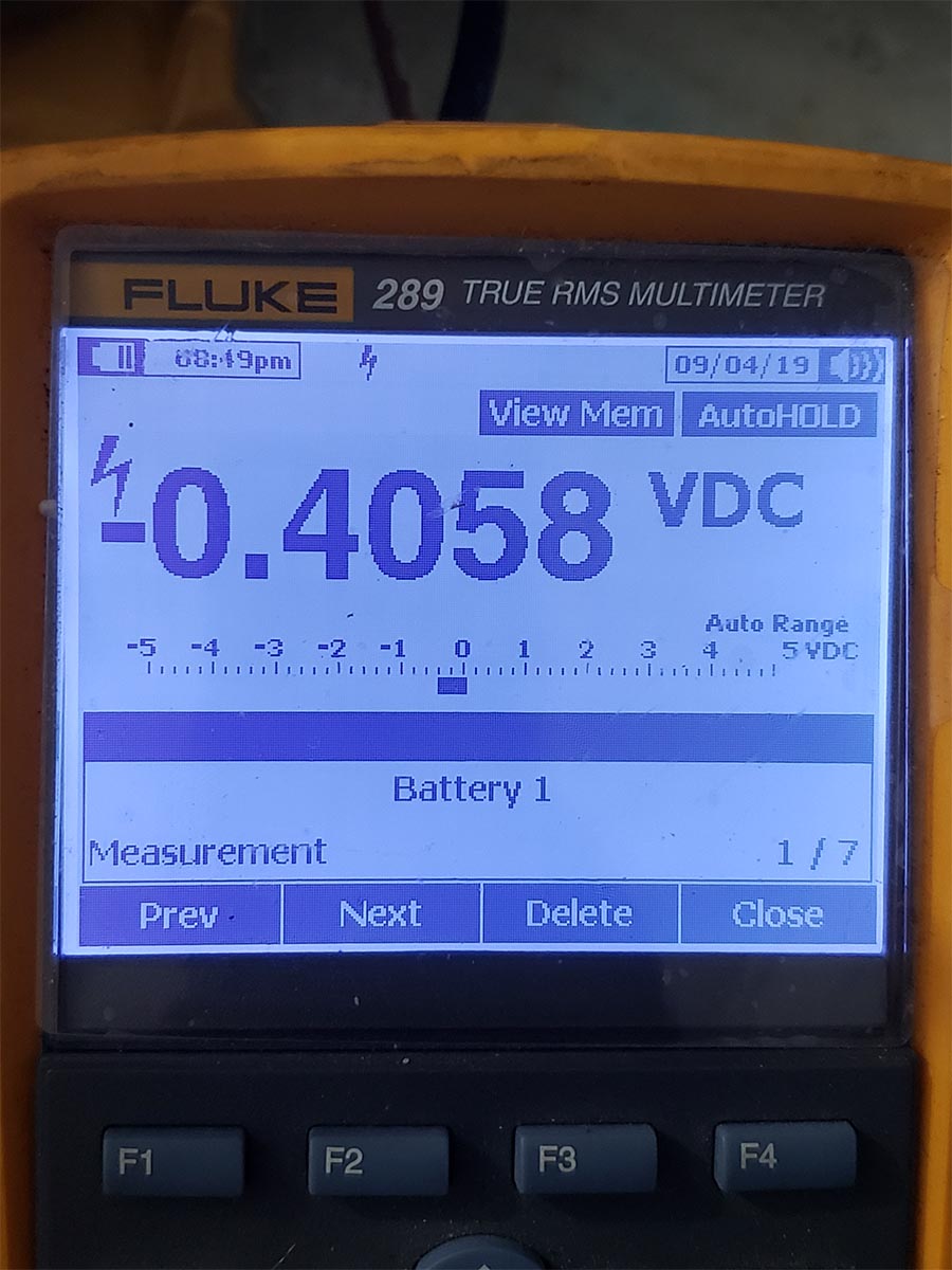
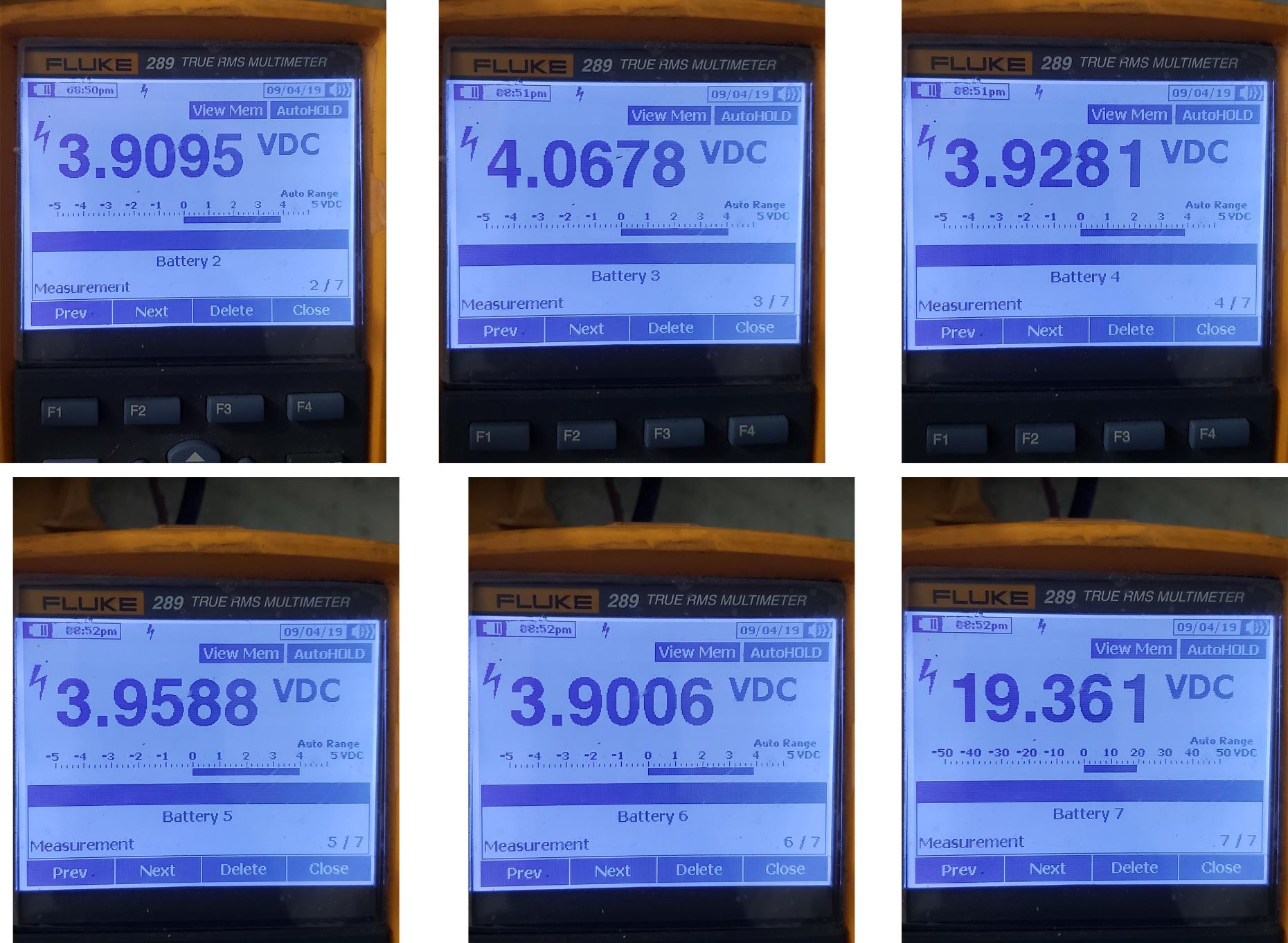
Cell bank #1: test Pins 0 and 1: *Battery 1 on DMM screen*: -0.4058V
Cell bank #2: test Pins 1 and 2: *Battery 2 on DMM screen*: 3.9095V
Cell bank #3: test Pins 2 and 3: *Battery 3 on DMM screen*: 4.0678V
Cell bank #4: test Pins 3 and 4: *Battery 4 on DMM screen*: 3.9281V
Cell bank #5: test Pins 4 and 5: *Battery 5 on DMM screen*: 3.9588V
Cell bank #6: test Pins 5 and 6: *Battery 6 on DMM screen*: 3.9006V
__________________________________
Module Total: *Battery 7 on DMM screen*: 19.361V (tested at main M8 terminals)

Sent these results over to the vendor, and he is now saying that the battery was “negative charged.”
I responding by telling him that the Victron MPPT is a computerized charger and cannot “negative charge” a battery – also noting that 5 out of the 6 individual cell sections are almost at 100% SOC.

Battery vendor now saying that “at some point you hooked it up backwards” – AFAIK, hooking up a battery to the Victron backwards would kill the Victron MPPT, not the Battery.
Furthermore, there’s no chance to connect anything backwards, since all connections are preexisting.


Original 2 Tesla modules I had were swapped back in 6:20pm (September 2) and from the same screenshots above we can see (3 days ago column, 2 days ago column, yesterday column and today column), the Victron MPPT charge controller continues to work flawlessly. (1.70V for V-min apparently shows that I changed the battery that morning. 8.26V for V-min apparently shows that I swapped the battery again but it recorded that swap on the morning of the first sunrise it saw on September 3, since it would have lost power.)


Received notification when charger switched to float mode,

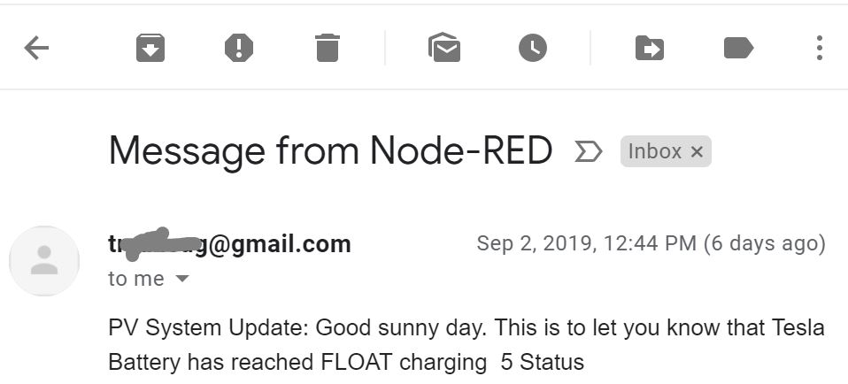
System errored out 15 minutes after that.


I also looked over the logs for charger status (3=bulk, 4=absorb, 5=float), voltages and temperatures on 3rd party monitoring also says the Victron MPPT works as it’s supposed to up until the time cell bank #1 of the Tesla Module seem to have died.

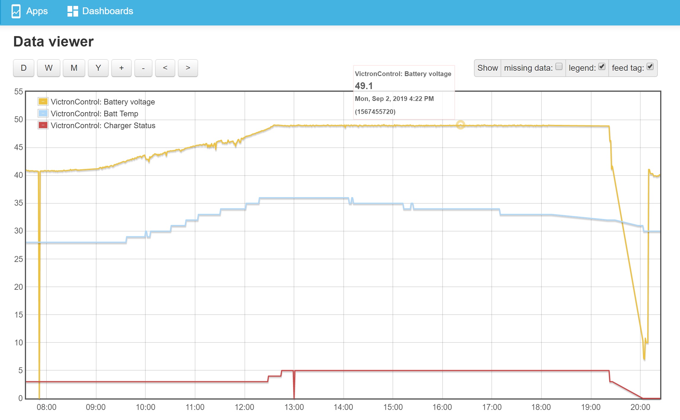
Charger status 5 after the error #38 spike and up to the time of disconnection seems like garbage data to me as you can see the temperature readings from the BMV showing a decrease meaning that both loads and charging were disconnected (switched back to Grid). (Times on graph above are 1 hour ahead.) Nothing else unusual was detected with the battery voltage on the monitoring until the Tesla modules were disconnected and tested separately with the Multimeter.

30 day history also shows this is the first time the Victron has ever posted an error. Row 6 is the day in question.


I would like to get the bad module I received replaced under warranty.

If it is that this data does not indicate that the module was delivered to me with a weak cell bank #1,

I’d like to know under what circumstances can a Victron Charge controller “negative charge” 1 cell block out of a 12S battery setup, while charging the other 11 seemingly okay.

I look forward to your responses.


Thanks.

chargersmart solar set-up help
nod-red.jpg (47.2 KiB)
data-viewer.jpg (279.0 KiB)
6s.jpg (308.4 KiB)
smartsolar.jpg (148.4 KiB)
relays.jpg (140.7 KiB)
cell1.jpg (140.2 KiB)
bluesolarhistory.jpg (290.7 KiB)
2 |3000

Up to 8 attachments (including images) can be used with a maximum of 190.8 MiB each and 286.6 MiB total.

4 Answers
Daniël Boekel (Victron Energy Staff) avatar image
Daniël Boekel (Victron Energy Staff) answered ·

Hi @brinx38

No matter what chargers / loads are connected to a battery, it cannot see nor cause a battery to get out of balance.

The reason you have a negative voltage over one of the cell groups, is that the battery has been out of balance, this is -VERY- dangerous, a reversed polarity happens when that cell (group) is empty before the rest of the cells, and as a result get all the current that flows trough the pack while they're empty, and after they reach zero volt, it will be a negative voltage.

Note that this doesnt happen while charging but while discharging.

The other way: during charging, in a pack that is out of balance, the highest charged cells will reach potentially dangerous levels while the total voltage seems ok.


All this is the reason you -MUST- use a BMS. (Battery Management System)

The most important function of a BMS is preventing over and under voltage in a cell, after that: measuring temperature and balancing the cells (to get them all to the same voltage)

In your case a BMS wouldn't have gotten your modules back in balance, but at least it would have prevented the reversed polarity by shutting down the system when a cell reached a low voltage threshold.


The most common reason for an unbalanced tesla battery module is: Coolant spills, if during disassembling the battery the coolant leaks and gets into the battery modules, it will form a conductive layer in the positive battery poles, this is AFAIK impossible to clean off, and a BMS cannot correct this issue (only detect it and prevent damage like burning due to overcharging of other cell groups)
Other reasons can be damaged bond wires to the cells due to abuse.


Please note that Tesla batteries burn very violently when overcharged or otherwise damaged, and take all use appropriate measures to assure safe use.

A BMS should have means of disconnecting the battery from the rest of the system, for example by using contacters or by using a trip-unit (shunt-trip) to open a breaker.

1 comment
2 |3000

Up to 8 attachments (including images) can be used with a maximum of 190.8 MiB each and 286.6 MiB total.

brinx38 avatar image brinx38 commented ·

Thank you very much @Daniël Boekel,

All that you have said is what I know to be true also from my days with LiPos and RC, but I needed to hear it from the authority.

Since the only time I discharged the bad module was after this all went down (for 30 seconds as mentioned in my post), and this was after disconnection, I suppose I received it with Cell Block #1 waaaaaay of balance and/or with internal coolant damage.

The logs say that that everything (including loads) got disconnected right in sync with the error #38.

The battery remained at 49.1 Volts until I disconnected it manually at 6:20pm. That sharp voltage drop you see to 8 Volts is me removing the battery and not a real discharge - just like the one at the beginning of the graph at 6:50am, which indicates exactly when I installed it.

I do have the BMS to be installed when I have the 4 modules in parallel (which was supposed to be today).

Thanks again.

Your response was much appreciated.


Total Battery Module lifespan: 6 Hours : 39 minutes

0 Likes 0 ·
Tom avatar image
Tom answered ·

I thing you got a bad module. I has a similar issue with a module I had to replace. Question do you have all the battery cables at the same length for equal resistance? Just a thought.


2 |3000

Up to 8 attachments (including images) can be used with a maximum of 190.8 MiB each and 286.6 MiB total.

brinx38 avatar image
brinx38 answered ·

Hi Tom, both my negative and positive 1/0 leads are very short (both measure 30" from battery terminal to bus bar). The Negative lead has the shunt for the Victron Battery monitor included in the 30 inches.

From Victron Charge controller to bus bars, both also very short at about 18 inches.

Thanks for your insight.

So reverse charging is a thing?

6 comments
2 |3000

Up to 8 attachments (including images) can be used with a maximum of 190.8 MiB each and 286.6 MiB total.

Tom avatar image Tom commented ·

Did you check the individual cell voltages before the first charge with a 6 cell battery medic or a volt meter? Yes I think your module is toast and if you try charging it again do it outside your RV and far from any buildings. Start with low amperage and measure the 6 cells with a battery medic like you use with your RC stuff.

0 Likes 0 ·

Please do not attempt to charge a damaged module.

Besides the risks, it is damaged and will not be usable.

0 Likes 0 ·
brinx38 avatar image brinx38 Daniël Boekel (Victron Energy Staff) ♦♦ commented ·

Thanks.

I have no intention of charging it nor discharging it ever again- I don't even want to go near it....

I'm looking into how I can dispose of it safely. The other module I got along with it seems fine though.
I hooked it up in series with one of my existing two (after matching the voltages of course), ran it with the Victron MPPT- Saturday, yesterday, today- no problem.

What I would like to know though - is it possible for the bad module to spontaneously catch on fire while just sitting?

Also, do you think it is safe for transport? I want to know this in case the seller wants to have it shipped back to him.

Finally, @Tom, I think I prefer this outcome. As @Daniël Boekel was telling us, no amount BMS would have prevented this, but would have detected the messed up cell block #1, showing me that it was waaay off balance from the get go. In that case, I would still be left with a damaged module I could not charge/discharge as the contactors would just trip on every attempt of use.

I didn't hook up the BMS because I didn't want to break the Teflon tape seal/clear plastic cover--- nor remove the original control board until I proved the modules worked (by cycling it few a few days) -lest there be a warranty issue and the seller decides that the issue was caused by improper removal of the control board.

What I do know from my own experience and from that of others is that these Tesla modules are extremely well balanced internally. The two original modules I have the internal cells came within 0.1Volts apart. That has not changed after 60+ daily charge/discharge cycles.

We are all aware that these modules are harvested from crashed/damaged vehicles.
Like @Tom also experienced, we would expect a small percentage of them to have internal issues due to the nature of the accident- hence why I only purchase those with a warranty.

Many thanks to you both for your input.

0 Likes 0 ·
Tom avatar image Tom brinx38 commented ·

I don't think the the module will combust just sitting. It would require an over charge above 25.2 volts or 4.20 volts in any one cell.

I do not think it is a good idea to charge or use the Tesla module with the Tesla BMS board installed and the 6 cell leads attached as you do not know if the board is trying to balance when charging.

The first thing I do with a Tesla module is test every cell group voltage with a volt meter and then connect the balancing leads to a Hobby King Battery Medic to see all 6 cell groups side by side and balance them with discharge resistance. After I find all in good standing then I connect it to my inverter charger and test charging and discharging under low amps. If that works well then I increase the Amos all while watching the 6 cells with the Battery Medic.

With regard to shipping back to the vendor I believe the battery must be discharged down to about 21 volts and has to ship ground per designated Li Ion regs. Fed Ex Ground or UPS Ground Freight will ship the battery. Your vendor you purchased from can help.

Have you looked closely at the battery? Are any of the 444 fused wire burnt off or broken? If so the battery may have shorted out.

Tom

0 Likes 0 ·
Meine_Energiewende avatar image Meine_Energiewende Tom commented ·

My way of using tesla cells is: bouht a simp bms unit which connects directly to the tesla onboard bms. Simp BMS is able to talk to venus or color GX. Looks like this:


0 Likes 0 ·
Tom avatar image Tom Meine_Energiewende commented ·

Very interesting. What does a BMS system like yours cost? The Tesla BMS boards in my modules were removed before they were shipped to me.

I have 2 Tesla modules in my RV and I was able to shoe horn them into my step battery box. Of course I has to modify it and I also have a liquid heating unit that can warm both modules when needed to charge. I also use the Tesla thermistors for my temperature monitoring.

0 Likes 0 ·
mike-wood avatar image
mike-wood answered ·

Interesting topic... I just got two Model S modules and my Multiplus 24/3000/70 and MPPT 100/50 are on their way. I have a simple Tenergy 5-in-1 balancer and will use it both on the cells first then compare each of the two modules (overall voltage) before connecting them in parallel. I am wondering if these little hobby devices can stay in place while charging and discharging.

First off, do folks trust the settings of the Multiplus and MPPT (and BMV712 with temp) to control charging limits. I know that a BMS would monitor individual cell-group voltages and stop charging - but is this a fault-state (ie. shut off system) or simply a stop-charging message and hopefully averting catastrophic condition that the two chargers did not detect themselves.

Low-voltage wise; I was hoping that a Smart Battery Protect on the 24VDC loads could shut off at 19V and I think the inverter stops at 19V also. I wonder if a low per-cell voltage detection is as important.

I wonder if the Victron equipment can take care of normal limits (low/high system voltage and low temp disabling) while a BMS really handles a more serious "fault" of a particular cell out range and uses a contactor to disconnect requiring manual intervention.

Have people successfully done this via V.E.Can or simply use the relay loops?

2 |3000

Up to 8 attachments (including images) can be used with a maximum of 190.8 MiB each and 286.6 MiB total.

Related Resources

Additional resources still need to be added for this topic