question

Dominic Porter avatar image
Dominic Porter asked

Solar disappeared now battery high cell alarm and not being used?

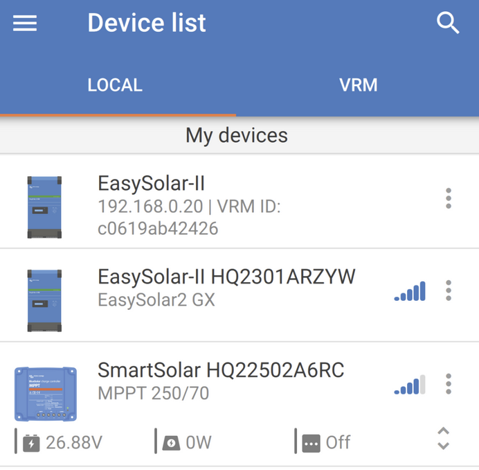
Hi I have and ESS setup with a Victron Easy Solar II GX, 2Kw of panels and 8xLifePO4 batteries in series with a 24v Daly BMS. It's been working for nearly a year with light use (just an extension lead) then finally connected the rest of the house a couple of weeks ago.

Yesterday was the second of a couple of cloudy days and the batteries dropped to about 20% overnight, so the low battery SOC kicked in and it was running the house off mains pass through. The sun came up and batteries started charging. At one point I saw them back up to 50% and pulling 1200W from the panels. So far so good...

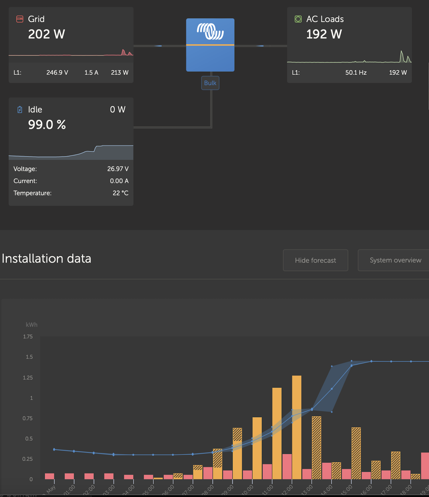
Sometime in the middle of the day, the solar part of my display just disappeared, ie the bottom right corner of the graphic which usually has 'solar' is just empty, like it doesn't exist. I know it was still charging because the grid power was at 0 and the percentage of the battery went on increasing until it was at 100%. I tried resetting the Victron box but no change.

This evening it's gotten even worse... the battery is not being used - all the house power is being drawn from the grid while the battery sits at 99%. On the BMS Bluetooth interface there is a 'high cell' alert and one of the cells is at 3.53V (instead of 3.33). Not sure what to do about this, it's never happened before... Also not sure why the solar part of my display has disappeared, both locally and on VRM.

Any suggestions?

1716243172422.png

ESSBMSEasySolar All-in-One
1716243172422.png (314.9 KiB)
2 |3000

Up to 8 attachments (including images) can be used with a maximum of 190.8 MiB each and 286.6 MiB total.

6 Answers
snoobler avatar image
snoobler answered ·

Troubleshooting:

  1. Reboot Cerbo.
  2. Power cycle MPPT (charger off, panels off, disconnect from battery, connect to battery, panels on, charger on)
  3. VE.Direct or VE.Can cable swap repeating #1 and/or #2.

Is the inverter charger absorption voltage set the same as the MPPT? If it's higher, you may trigger OVP.

2 |3000

Up to 8 attachments (including images) can be used with a maximum of 190.8 MiB each and 286.6 MiB total.

Dominic Porter avatar image
Dominic Porter answered ·

OK so I did this as far as I can - it's an all-in one so can't power off individual component, but I disconnected the panels, diconnected battery, turned off mains in and tuned off the Victron Switch. No VE.Direct or VE.Can cables involved, although I believe there are internal connections between the separate devices?


No change. why would the solar charge component of my display just disappear? Could this be a fault with my Victron device? It seems like when the Solar charger 'disappeared', the battery carried on charging until it hit the high voltage alarm on my BMS and disconnected.

1 comment
2 |3000

Up to 8 attachments (including images) can be used with a maximum of 190.8 MiB each and 286.6 MiB total.

snoobler avatar image snoobler commented ·
Sorry. Totally spaced that it's an EasySolar.
1 Like 1 ·
nickdb avatar image
nickdb answered ·

There are many reasons, and usually related to configuration.

The PV tile is missing completely. Try connect to the built in MPPT via blueteeth, see if it is accessible and if it reports any errors.

How has the inverter been configured? Post your settings.

Did you check the PV string to make sure it is operational? Any chance you exceeded Voc?


The cell voltages will be down to the battery and/or BMS config. Unfortunately par for the course on DIY systems. Imbalances often appear after a deep discharge/charge cycle.

Would suggest you get someone to help you check the battery thoroughly, too many variables to triage via the interweb, as an unsupported battery there won't be much support. Have a search on the modification section for your BMS type, might be something to point you in the right direction.


3 comments
2 |3000

Up to 8 attachments (including images) can be used with a maximum of 190.8 MiB each and 286.6 MiB total.

Dominic Porter avatar image Dominic Porter commented ·

> The PV tile is missing completely. Try connect to the built in MPPT via blueteeth, see if it is accessible and if it reports any errors.


1716276325328.png

From the app... I can't see any errors.


> How has the inverter been configured? Post your settings.


Inverter settings I don't think I have messed with... where do I see them to post?

1716276629127.png

> Did you check the PV string to make sure it is operational? Any chance you exceeded Voc?


Looks like this is when something happened (ie 1205 yesterday). Max voltage on the device should be 250 so well under that.


> The cell voltages will be down to the battery and/or BMS config. Unfortunately par for the course on DIY systems. Imbalances often appear after a deep discharge/charge cycle.


It did a deep discharge/charge yesterday as I said and it is the first time the Victron box hit the low battery SOC value and cut off the battery (at 20%).

This morning one of the cells was at 3.66V - higher than before I went to bed, so I think it was continuing to charge the battery despite it being at 100%? Panels currently disconnected and charger turned off via Victron app. The high cell is slowly coming down (3.546 whilst others are at 3.339).

0 Likes 0 ·
1716276325328.png (171.3 KiB)
1716276629127.png (233.0 KiB)
nickdb avatar image nickdb ♦♦ Dominic Porter commented ·
Mppt state says off. Select it and see why.
0 Likes 0 ·
Dominic Porter avatar image Dominic Porter nickdb ♦♦ commented ·

Panels were disconnected... I was getting concerned seeing the battery voltage go up and up.


So BMS alarm has cleared now and inverter is doing it's thing, battery cells seem normal, solar charger is working as seen on the bluetooth connected app, but the console display still shows no Solar: 1716278928209.png

1716279060299.png

0 Likes 0 ·
1716278928209.png (112.3 KiB)
1716279060299.png (209.2 KiB)
ejrossouw avatar image
ejrossouw answered ·

What do you see under device list? If it still shows, delete it to be rediscovered. Has BOTH the inverter and MPPT been programmed with the correct charge parameters for your batteries?

2 comments
2 |3000

Up to 8 attachments (including images) can be used with a maximum of 190.8 MiB each and 286.6 MiB total.

Dominic Porter avatar image Dominic Porter commented ·
See image above. Tried doing 'forget' and readding but no change.
0 Likes 0 ·
Dominic Porter avatar image Dominic Porter Dominic Porter commented ·

PS I believe all config is correct. will triple check... It has been working since last August with no problems but yesterday was the first time it went down to 20% and BateryLife kicked in.

0 Likes 0 ·
Alistair Warburton avatar image
Alistair Warburton answered ·

Have you tried redetecting your system on the GX? I had to do it once, cant think why.

Obviously everything will need to bee powered up but If it were me I would be stopping all charging and putting the inverter in off mode just t be safe. I would also back up everything that is accessible up first.

I had a quick look and didn't find a procedure. The CCGX manual describes redetecting the inverter/charger and doesn't have any associated warnings.

I may be talking rubbish but its probably worth you looking to see if it could help, unless you know it isn't going to. I cant say one way or another to be fair but thought it was worth putting out there. Worst case I get corrected and learn something.

I hope you get you system sorted.

1 comment
2 |3000

Up to 8 attachments (including images) can be used with a maximum of 190.8 MiB each and 286.6 MiB total.

Dominic Porter avatar image Dominic Porter commented ·
I have tried redecting several times, but to no avail.
0 Likes 0 ·
Dominic Porter avatar image
Dominic Porter answered ·

Update on my saga... I have updated all my firmware and spent quite a while on the phone to my supplier's tech support. They were quite surprised that my BMS had no data connection to the Victron box, so the only info the system goes on is battery voltage. I guess this is fairly common though? My BMS is a Daly 24v 8s.

Anyway, we identified one thing wrong in the MPPT battery settings - the profile was set to 'Rotary Switch' instead of 'Preset' and LiFePO4 battery. In practise this meant that the float & absorb values were a bit higher than they should be. I didn't even know this setting existed, and the ESS instructions say that the Solar charge controller will follow the profile configured in ESS setting. Looking at the battery voltage history in the MPPT it did max out at 30v on the day things went wrong so maybe this is what caused the issue?

SO current state is that although the Solar MPPT is there and seems to be working (I have full access via bluetooth) it does not seem to be connected to the VE bus, so no solar charge data is getting through to the rest of the system. In practise this means that it is registering power out, but not counting (solar) Watts in... so yesterday evening the battery voltage was well over 26v but the ESS shut off the inverter because it thought it was at 0% (BMS bluetooth app had it at about 50%). Since then I updated the firmware on the Multiplus and had to run VEConfigure again to setup ESS...now it says battery is 100%, despite the BMS telling me it is over 50%.

Is it possible that the high battery voltage (which caused my BMS to shut down) caused some damage to the VE bus comms port on the solar charger? Or the cable? I wouldn't have thought this possible, but they do always say "Don't connect panels without a battery". I've opened up the EasySolar box and don't see anything obviously wrong with the bus cables. Thoughts?

4 comments
2 |3000

Up to 8 attachments (including images) can be used with a maximum of 190.8 MiB each and 286.6 MiB total.

Alistair Warburton avatar image Alistair Warburton commented ·
Try the re-detect, now that you have updated and established that everything is powered on an appears to be working, you don't have anything to loose.

Also make sure you have a bus terminator wherever you need one, check the wiring guide because I cant remember if you need one on both ends or just the last device that is not a GX.

0 Likes 0 ·
delf67 avatar image delf67 Alistair Warburton commented ·
Termination resistors are for canbus not ve.bus.
1 Like 1 ·
Alistair Warburton avatar image Alistair Warburton delf67 commented ·
Sorry, silly error. I should have checked the documentation myself!
0 Likes 0 ·
Dominic Porter avatar image Dominic Porter Alistair Warburton commented ·
It's an EasySolar device. All the connections are inside the box and I didn't set them up.
0 Likes 0 ·