question

obyhun avatar image
obyhun asked

3 phase to 1 switch + bypass wiring

This is a solution for emergency cases when no power available and loads are within 1200W.

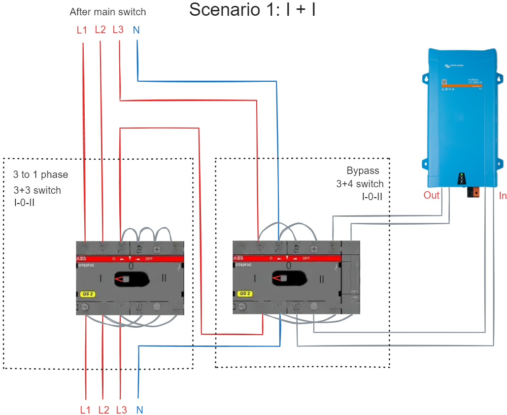
I have 3 phase power in my apartment and Multiplus II 48/1600 for backup. The idea is to put 2 switches (3+3 and 3+3 with extra module) in the middle after the main switch like this (Scenario 1). When they're both in position "I", all 3 phases work as usual, Multiplus isolated.

1714953835921.png


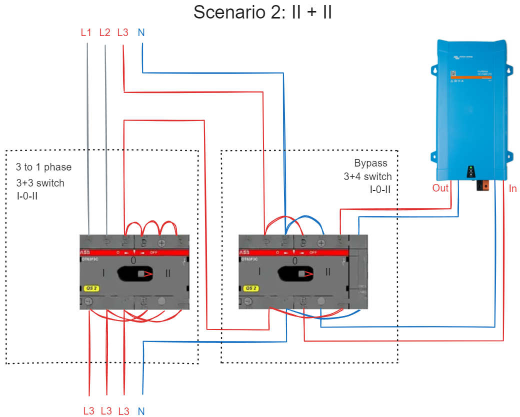
When grid power is gone, I can manually switch both to position II (Scenario 2). Now the apartment is powered from L3 that is backed up by Multiplus.

1714954358651.png

1. What happens if the first switch is turned to position "I" before the bypass by mistake (Scenario 3)? In this case N goes through Multiplus, but all 3 phases connected.

1714954605001.png

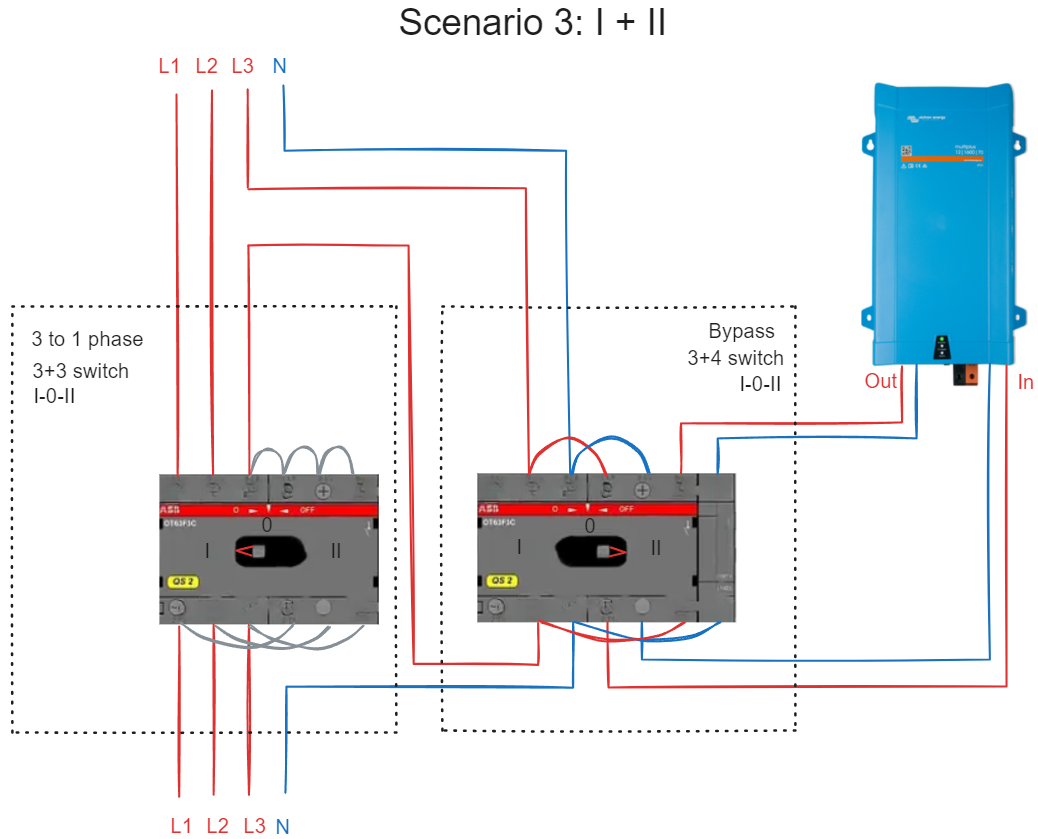
I see 4 possibilities if load applied to other phases:

  • Multiplus is fried;
  • Multiplus falls to error mode;
  • works fine if total loads are within 16A (Multiplus transfer switch limitation);
  • all works fine.

I'm not an electrician and made this scheme intuitively.

2. I'd appreciate if someone could share a ready-made solution.


wiring3 phasewiring diagramswitch
1714953835921.png (179.8 KiB)
1714954358651.png (178.1 KiB)
1714954605001.png (181.6 KiB)
2 |3000

Up to 8 attachments (including images) can be used with a maximum of 190.8 MiB each and 286.6 MiB total.

2 Answers
Matthias Lange - DE avatar image
Matthias Lange - DE answered ·

If you want to use ESS the MultiPlus has to be on L1.

Im many countries the normal MultiPlus is not allowed for ESS use, you need to use a MultiPlus-II.
You need to check that!

https://www.victronenergy.com/media/pg/Energy_Storage_System/en/index-en.html


NEVER switch the N unless you also switch the phases with the same switch at the same time!
If you bypass is OFF you don't have a N in your house that can cause a voltage spike and can fry your loads!

You only need one switch (there are no fuses, RCD and other needed components in this schematic!).

1714974404408.png


1714974404408.png (38.0 KiB)
4 comments
2 |3000

Up to 8 attachments (including images) can be used with a maximum of 190.8 MiB each and 286.6 MiB total.

Delta Victor avatar image Delta Victor commented ·

I would also put an automatic breaker between the grid and the multiplus ac in. So in case of maintenance, you're able to disconnect it from the grid.

Also make sure that there are no 3phase devices connected after the transfer switch.

Very important is that the transfer-switch goes over a zero connection point 1-0-2

You can use one like the

- Hager Him 406

- ABB OT40F4C

- Schneider INS250 31145

-...

2 Likes 2 ·
obyhun avatar image obyhun Delta Victor commented ·

ABB OT63F3C (I-0-II) is what I was going to use, but my schema is not fool-safe. As @Jetlag advised, there's a special switch for this use case. e.g. Sontheimer ULO63/4T/NS/Z101/F976.

0 Likes 0 ·
jetlag avatar image jetlag Delta Victor commented ·
I'm not sure if these types provide the neutral leading and lagging functionality. At least the Hager and the ABB does not seem to provide it. The Schneider could have it, but anyway is way oversized and too expensive.
0 Likes 0 ·
obyhun avatar image obyhun commented ·

First of all, thank you @Matthias Lange - DE. Very clear answer.

1. I have a Multiplus II (2nd gen), should be no problem.

2. Why Multiplus has to be on L1?

3. What software do you use for these schematics? Really appreciate you spent time to draw this.

That's what I'm going to do. ABB OT63F3C + 2 attached modules.

1715045182273.png


0 Likes 0 ·
1715045182273.png (159.3 KiB)
jetlag avatar image
jetlag answered ·

There are special Switches for that, like Sontheimer ULO63/4T/NS/Z101/F976 or the Kraus & Naimer KG20A K950 VE2 F437.

These switches are more expensive, but they provide all you need. Especially the leading and lagging Neutral is very important as Matthias already mentioned. Otherwise you risk a zero point shift and the voltage might exceed the limits and destroy your connected devices.


I have such a Sontheimer in my 3-phase installation for exactly the same case.

5 comments
2 |3000

Up to 8 attachments (including images) can be used with a maximum of 190.8 MiB each and 286.6 MiB total.

obyhun avatar image obyhun commented ·
Thank you very much! I'll go with ABB OT63F3C + 2 modules and replicate the same wiring (see the schema in the comment above), because I already have it. Double connections with double wire ferrules. The switches you showed are actually cheaper.
0 Likes 0 ·
jetlag avatar image jetlag obyhun commented ·

I just checked the ABB OT63F3C and it seem not to have this Neutral lagging + leading functionality... But this is the key for what you are going to do with this switch.

Its not just a "standard" multi-pole switch you need. A lot people just think they can use a standard and don't understand why these special switches are more expensive.

Please check again if this shwitch provides this funciton, otherwise take another one.

1 Like 1 ·
obyhun avatar image obyhun jetlag commented ·

I bought the Sontheimer. But I don't understand what Neutral lagging + leading functionality is, tbh. And couldn't find the detailed specs.

0 Likes 0 ·
jetlag avatar image jetlag obyhun commented ·

I'll try in to explain in an easy way...

You might know, that in a 3-phase System the voltage between two phases is ~400V (because ot the angular offset of 120°). The voltage between one phase and neutral is ~230V.

If you now switch between to voltage sources, especially between two 3-phase sources (or in your case back from your offgrid 1-phase supply back to the 3-phase grid supply), then it is important to first create/provide the reference voltage. And this is the neutral potential.

If you do not, because your change-over switch just connects all 4 pins in parallel, then for a short time the voltage reference (neutral) for the phases could be missing, and a higher voltage up to ~400V could appear on the life-wires.

The point is, with such a normal change-over switich you can't be sure, that neutral is connected first, so you have to chose a change-over switch, that will ensure this. If neutral is connected first (just a few milliseconds earlier), than all is fine. But this must be given by the mechanics of the switch.

The same problem you also have when disconnecting from one supply to another. You might loose neutral first, and then again the reference would be missing. That's why netraul is always the first that is connected and the last that is disconnected.

Hope this is fine enough for you. ;-)


It is a complicated topic, and often forgotten, - even by the switch manufacturer. It sometime is really hard to find out if this is supported or not in their documentations.

1 Like 1 ·
obyhun avatar image obyhun jetlag commented ·
Thank you! I gave you all my points :)

I guess when a manufacturer marks a pin as N, it inexplicitly means the feature is supported.


0 Likes 0 ·