question

polarseal avatar image
polarseal asked

Orion smart engine Switch

Hello,


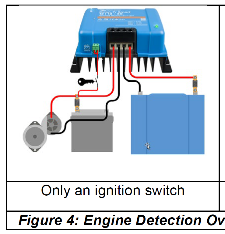
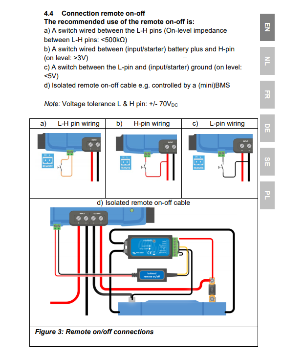
I'm getting a bit confused by the wiring diagram in the Orion smart manual. In this figure (most are very hard to see in the manual it show the ignition switch wired to the engine ignition power and them going to the H pin. but it also shows a bridge to the L pin. If im not mistaking adding this bridge will keep the unit always on..


I would like to have the unit charge from my house bank to my starter and bow thruster bank. I would like this charging to happen only when the engine is on.


orion-tr smartwiringwiring diagram
1589244838478.png (261.1 KiB)
4 comments
2 |3000

Up to 8 attachments (including images) can be used with a maximum of 190.8 MiB each and 286.6 MiB total.

andy-baird avatar image andy-baird commented ·

I have the same question, which I (mistakenly) posted as an answer--see below. Victron... how about clearing this up for us, please?

0 Likes 0 ·
edclarke avatar image edclarke commented ·
This is very helpful! Does anyone know if it's possible to disable charging by applying +12V to either/both the L or H pins. I'm trying to charge a van starter battery from the house battery when the ignition is off, but want to ensure the this DC-DC charger is off when the ignition is on, and another DC-DC charger is charging the house batteries from the starter battery.
0 Likes 0 ·
kevgermany avatar image kevgermany ♦♦ edclarke commented ·
See my answer to your other post. Please don't double post your questions.
0 Likes 0 ·
Mark avatar image Mark edclarke commented ·

if You’ve got a bmv installed,you can use the relay to switch the DC-DC off,by detecting the voltage rise of the alternator on the starter battery.I have this set up in my camper van….works flawlessly

0 Likes 0 ·
5 Answers
andy-baird avatar image
andy-baird answered ·

I've also been waiting for an answer from Victron to polarseal's question.

In a nutshell: the manual says (fig. 1) that if L and H are bridged, either by the factory-installed bridge or by an external switch, the unit will be on. It goes on to say that if terminal H is brought high (>3V), or if terminal L is brought low (<5V), the unit will be on.

Figure 3 purports to show these three scenarios, but unfortunately figure 3's resolution in the manual is so poor that it makes the connections and labeling illegible. Figure 4 is readable, but it shows a bridge between L and H in addition to an ignition-controlled (positive voltage) input which--because of the bridge--is going to both pins.

Hence polarseal's question (and mine): is Victron really saying that both L and H would be brought high in this "Only an ignition switch" scenario? Is this perhaps related to disabling the "engine on detection" feature?

We really would appreciate an authoritative answer from Victron. The low-res illustrations in the manual make it impossible to see just what's going on with these L and H terminals, and the written explanations appear to be ambiguous or contradictory.


1 comment
2 |3000

Up to 8 attachments (including images) can be used with a maximum of 190.8 MiB each and 286.6 MiB total.

bathnm avatar image bathnm commented ·

Having tested, it is actually clear. If the L and H are bridged as per Figure 3 (a) then the software defined engine detections controls when the unit will charge. So if this is set to 14.5v, the unit will not charge until 14.5v is seen on the input.

If H is high s per figure 3 (b), then the unit is on and will start charging when the input voltage reaches 14.5, if H is low the unit is disabled.

If H is high and the voltage is below 14.5, but >7v is applied to L as per figure 4 (b) then the unit will start charging. If when L drops to < 7v the input is at 14.5v, the unit will continue to charge,

I agree the resolution of the diagrams are poor. Please also note that figure 4 (b) is different in the non-isolated to isolated manuals.

0 Likes 0 ·
Mark avatar image
Mark answered ·


I've had my Orion Dc/Dc charger running in my van for a few months automatically without any issues, by leaving the remote bridge in, the unit senses the ‘engine run detection’ Mechanism which basically Only kicks in when the alternator voltage rises above the ‘input voltage lock out’ parameter(set in the app)....basically plug’n’ play.
at first I left the bridge in and connected an ignition switched supply to h terminal with the link as per the diagram,the charger engaged as soon As the ignition was on,however if you just switch the ignition on and don’t have the engine Running then the charger is working!!.

(the above method overrules the engine detection system)
so you really need an engine run signal to use this option!

so Ive left it automatically With just the bridge in place,with no problems.

2 |3000

Up to 8 attachments (including images) can be used with a maximum of 190.8 MiB each and 286.6 MiB total.

andy-baird avatar image
andy-baird answered ·

Thanks for responding, Mark. OK, if I understand correctly, when the bridge is in place, the "engine on detection" feature will switch on the Orion unit when it detects a voltage rise on the input side (start battery). That could be from the engine running, but could also be from just switching on the ignition (maybe in "accessory" position?)

So adding a wire and switch as shown in Figure 4 lets you instead manually control the Orion device's operation, if desired, and disables the "engine on detection" feature. Right?

Now another question arises. A Victron dealer told me that in "engine on detection" mode, the Orion draws more standby current than if it is manually switched on and off. Can anybody verify this? I don't want to run my batteries down when the boat is not in use. It would be good to get a definitive answer from Victron about this.

4 comments
2 |3000

Up to 8 attachments (including images) can be used with a maximum of 190.8 MiB each and 286.6 MiB total.

andy-baird avatar image andy-baird commented ·

Please ignore my previous post; I mixed up some terms and it was confusing. Let's try again.

Thanks for responding, Mark. I understand that when only the bridge is in place, the Orion will start charging when it detects charging voltage on the input side.

I'm given to understand, however, that having just the bridge in place, as you are, keeps the unit in some type of "standby" mode which draws more power than polarseal's "only an ignition switch" method.

For this reason, I am interested in polarseal's question, because apparently when the unit is using the "only an ignition switch", then the standby power is either reduced or eliminated (?).

0 Likes 0 ·
rodneyab avatar image rodneyab andy-baird commented ·

@Andy Baird I simplified my use of the Orion by replacing the bridge wire with a longer loop that includes a simple on-off switch. Most of the time I have the switch in off position, and turning the engine on and driving the Orion remains off. If I want to use the Orion, I flip the switch on, drive, stop, engine off and Orion off, start engine and Orion is on again. In my use, I am not concerned with standby power use reduction, so can not clarify about that.

0 Likes 0 ·
coopfun avatar image coopfun rodneyab commented ·

sounds like a simple solution. can the unit be engaged or disengaged remotely by using the app?

0 Likes 0 ·
Mark avatar image Mark coopfun commented ·

Yes it can,

if you go into the demo library of the victron connect app,then you can get a feel for it

1 Like 1 ·
Margreet Leeftink (Victron Energy Staff) avatar image
Margreet Leeftink (Victron Energy Staff) answered ·

We are saying that if L (or both L and H) are high, the engine detection mechanism will be overridden. This means that the charger is on when pin L is high (>7V) and the engine shutdown algortithm is not active.

When pin L (or both L and H) is low (<7V) the charger is still on but now the engine detection is active.

I hope this makes sense. It is not an easy process to describe.

I agree that figure 3 and 4 in the manual are very hard to read. I will see to that that they are improved.

2 |3000

Up to 8 attachments (including images) can be used with a maximum of 190.8 MiB each and 286.6 MiB total.

Robert avatar image
Robert answered ·

The H pin from the website photo shows it on the RIGHT.

The H pin from the manual extract is on the LEFT. See b) H-pin wiring.


I can confirm that you need to pull the H pin high to turn the device on and that this pin is on the right side of the connector, making the manual diagram incorrect.


hqimage.png (352.3 KiB)
diagram.png (93.7 KiB)
2 |3000

Up to 8 attachments (including images) can be used with a maximum of 190.8 MiB each and 286.6 MiB total.