question

logic28 avatar image
logic28 asked

Adding one Multiplus in parallel

I’ve read most of the posts on this topics but did not find the answer that I was looking for

It s almost invariably stated that all inverters in one system should have equal cable lengths.

I’ve also read exceptions like: “unless you have gone as big as the terminal can take”

Question:

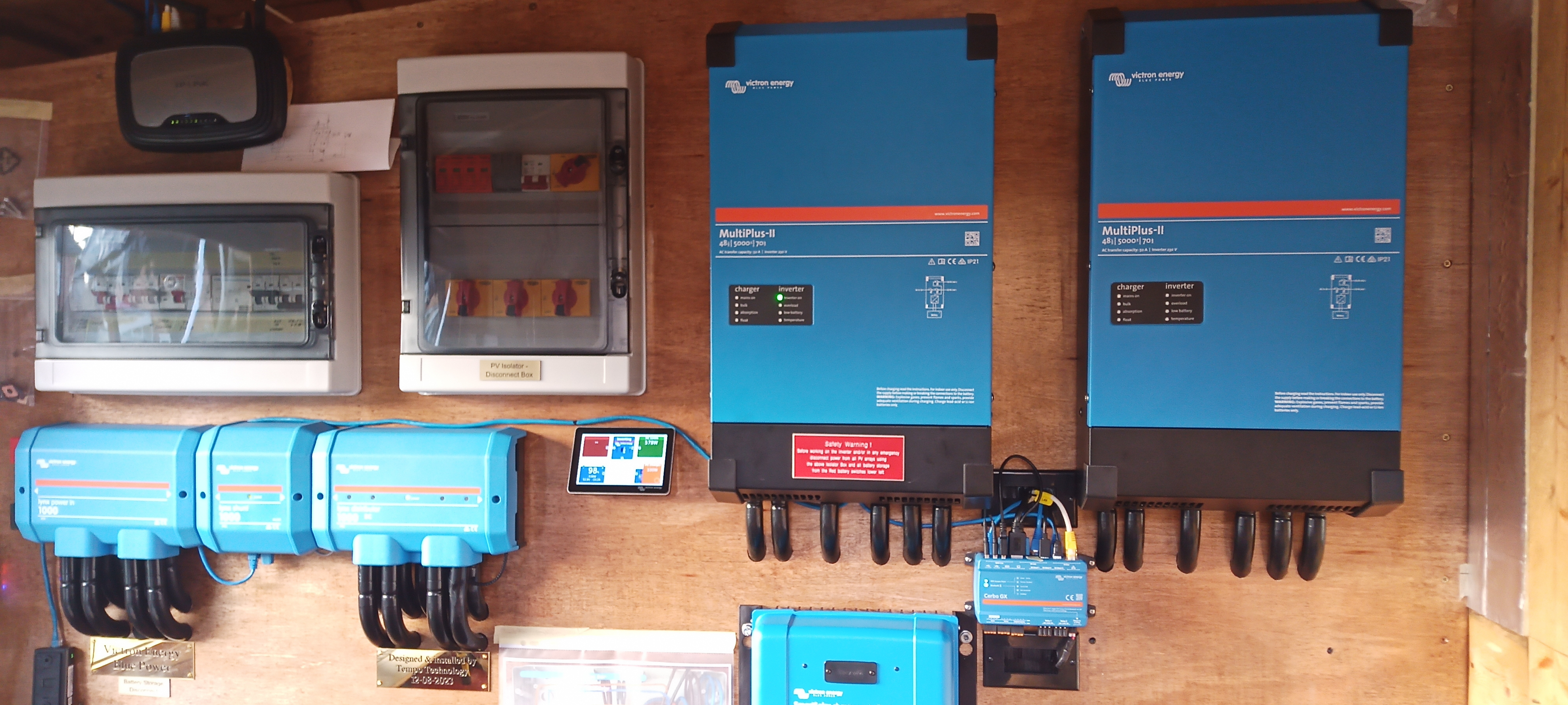
In an off grid system I am adding a second Multiplus II 5000 in parallel only centimetres away from the closest one to the Distributor and lengthening the shorter DC cables enclosed in trunking (currently 1m), would make for a very messy arrangement.

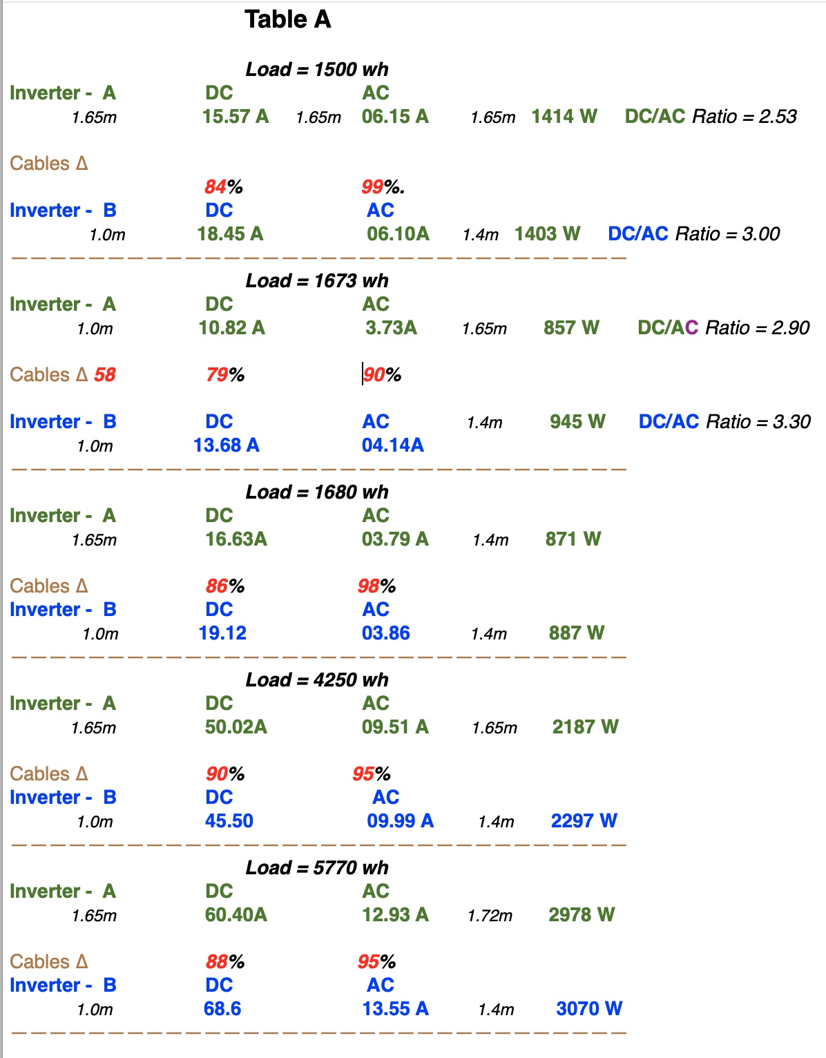
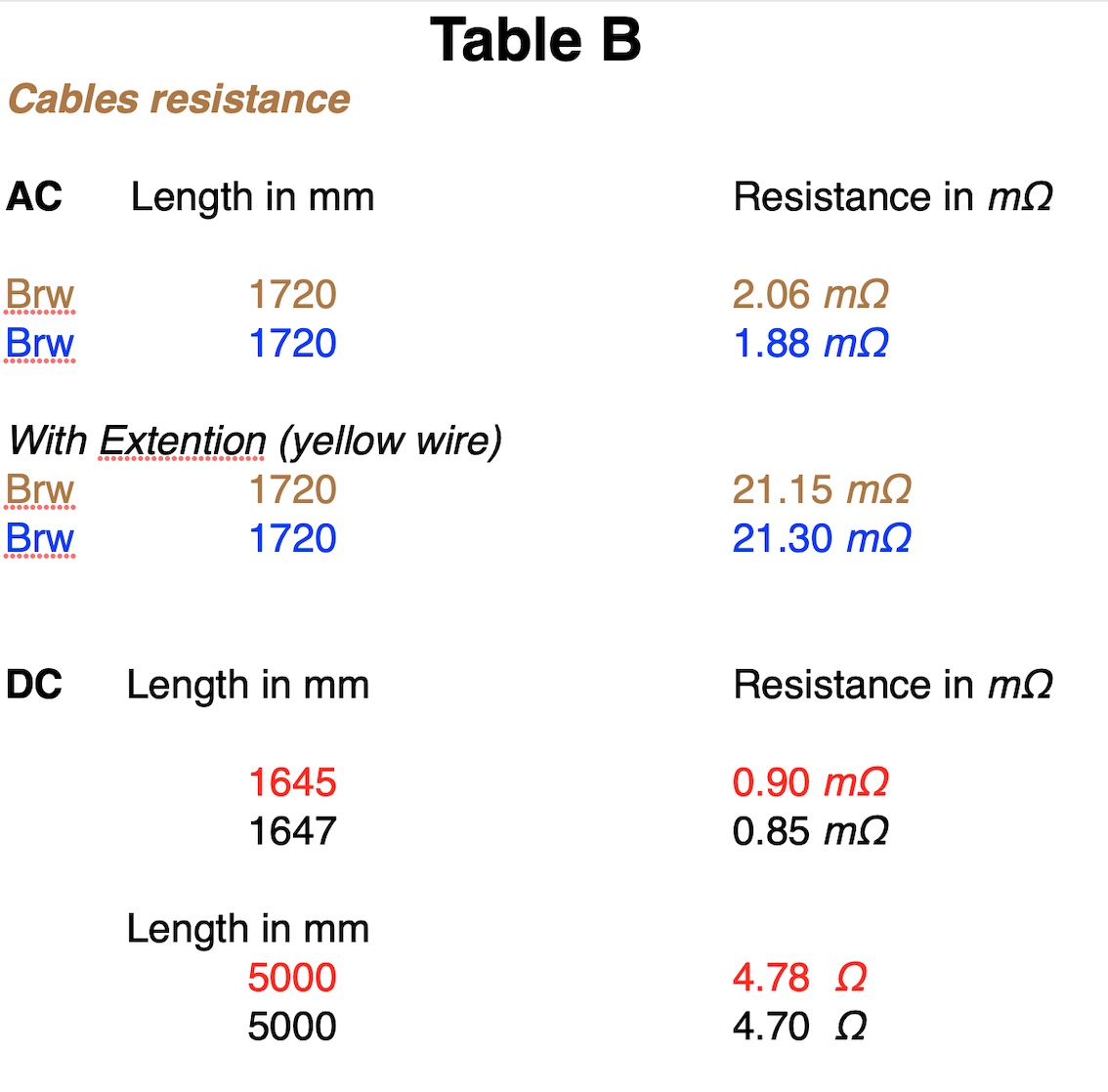
Since I am using 2/0 Awg (70mm) cables for both, I am wondering exactly what impact would the extra 35cm DC cable on the second unit have on the system.

I would have thought that 70mm section was large enough not create a signifiant resistance delta.

If, again as stated in various discussion because of the Dc lengths difference the AC system would draw more from the closest inverter and I was to quantify this by testing the passing Amperage discovering that a minor differential did exist, where would the problem be?


The AC side is not a problem and I can easily match the lengths


Thanks


multiple inverters
2 |3000

Up to 8 attachments (including images) can be used with a maximum of 190.8 MiB each and 286.6 MiB total.

4 Answers
Delta Victor avatar image
Delta Victor answered ·

I was planning to answer your question but because this is asked so many times, i will just give a quick hint:

If you had used the search function with terms like 'parallel dc cable length tolerance' you could have found this thread.

I think all of your answers are in there

2 |3000

Up to 8 attachments (including images) can be used with a maximum of 190.8 MiB each and 286.6 MiB total.

logic28 avatar image
logic28 answered ·

Thanks,

of course I have used the search and read many similar threads but as I said, none of them talks about the actual impact on the system.

I guess my question is, does it really matter if one inverter delivers a little more than the other?

Or is the imbalance causing problems with the synchronisation?

The thread from your link refers to Multiplus in ESS mode aansluiten op Belgisch net voor thuisbatterij. "

It is a totally different situation, my system in not connected to the grid beside the fact that most of it is not in English.


Cheers


6 comments
2 |3000

Up to 8 attachments (including images) can be used with a maximum of 190.8 MiB each and 286.6 MiB total.

nickdb avatar image nickdb ♦♦ commented ·
They will never be symmetrical, only question is how big is the gap. Too big and you have issues. Get a clamp meter. Measure the balance, if they are way off, then make changes.

Get the AC cabling right, that is more important than a small battery cabling difference.

If supplying loads is unbalanced, so will everything else.

1 Like 1 ·
logic28 avatar image logic28 nickdb ♦♦ commented ·
Thank you,

That is what I had in mind all along and I'm sure the answer will be in the readings from the clamp meter.

Cheers


0 Likes 0 ·
Delta Victor avatar image Delta Victor commented ·
It looks like i pasted the wrong link in my previous post, I have edited by now.


I would suggest to follow the manufacturers installation instructions.
But keep in mind that it's almost impossible to get perfect balance, the better you try the less your equipment wil suffer.

Don't forget that every connector crimp, every fuse, the torque of the bold automatically will give some imbalance.

As i remember correctly the wiring unlimited book explains some of the problems that can occur due to cable resistance.

Please make sure that the AC cabling is equal, has a calculated section and is not to thick. Also keep them separately fused, with the same type of fuse.


0 Likes 0 ·
logic28 avatar image logic28 Delta Victor commented ·

Thanks for the link, it was very helpful, my AC out is wired with 16mm cable, the same as all the rest of my AC wiring to the building distribution. It will be perfectly equal and the two inverter lines terminate into two identical breakers. (the image shows the 4 holes beneath the nº2 inverter where the second MPPT normally fits) img-20240309-165958-252.jpg

I was thinking of using a disconnect on each DC input line but I don't like the idea of having to many contractors along the system as they all add potential risks especially with 2/0 (70mm) cables in conjunction with DC devices that specify, for the same model, 200A from one vendor and 1000A from another so I think I might just stick to direct lines from the Distributor to the inverters.

The disconnect however would have come in handy if I ever wanted to temporarily revert to single inverter arrangement.

I have ordered more than enough fresh cable for the DC runs to be identical however, purely as a didactical exercise, I want to first run some tests with the 40cm discrepancy (only on the DC side) just to see what happens at various loads. I suspect that we will only see an imbalance (if any) at very high loads where the resistance of the 70mm wire starts to come into play.

Also I shall finally trim all DC and AC cables by testing their resistance with a dedicated instrument, an exercise that reminds me of when I used to tune the exhaust manifolds of my racing Porsche 911s by trimming them on my Superflow Engine Test Bench :)


0 Likes 0 ·
Delta Victor avatar image Delta Victor logic28 commented ·
Once the two inverters are programmed to work as one, it's not possible to just run one without reprogramming them.

So individually disconnecting them is not really needed. When doing so they wil show you this error.

If you would like to run just one of them, you can just power one of and reprogram the other one.


I'm interested to see the results once you start micro-Ohm-ing your installation.

0 Likes 0 ·
logic28 avatar image logic28 Delta Victor commented ·

I have only tested the new AC run today and will test the shorter run for comparison as soon as I can disconnect the currently running inverter and report here, however I've already cut the same length to be fitted so they'll be equal.

I'll test the DC side too and and report my findings here soon for both DC and AC .

As far as the reconfiguring I' am aware of that but in the event of a Multi failure I might have to do that temporarily in which case the isolators would come in handy, I just have to find some substantial ones, something that won't add thermal risks.

0 Likes 0 ·
nickdb avatar image
nickdb answered ·

It's a bad idea putting an mppt beneath the inlet of the inverter.

Those mppts generate proper heat, which will rise and feed into one of the inverters, causing elevated temperatures, premature derating and asymmetry.

It is good practice to isolate inverters from each other, for safety.

I have on more than one occasion needed to reprogram to standalone, so that is a nice to have.

5 comments
2 |3000

Up to 8 attachments (including images) can be used with a maximum of 190.8 MiB each and 286.6 MiB total.

Delta Victor avatar image Delta Victor commented ·
It's therefore also advised to mount them on a non-flammable substance.

I dont think plywood is intended for that.

0 Likes 0 ·
logic28 avatar image logic28 Delta Victor commented ·

I see them often mounted on wooden materials, especially on boats beside the whole building is in timber anyways so the risks are similar, the only answer would be to put an aluminium sheet behind them.


0 Likes 0 ·
logic28 avatar image logic28 commented ·
Sure, that is what I intended to do but wouldn't you be worried about the contacts reliability compared to a fixed cable? Any extra point of potential resistance is a recopy for problems, wouldn't you agree? I need to be sure that the isolators are up to the load of a 2/0 cable.
0 Likes 0 ·
nickdb avatar image nickdb ♦♦ logic28 commented ·

Why? That is how it is installed in most installations. I’d only be worried if you don’t choose good components and don’t believe you can make a good quality connection.

0 Likes 0 ·
logic28 avatar image logic28 nickdb ♦♦ commented ·
I have no means to test components that I purchase, I will have to use what I have used for all the batteries but I do not feel very safe when they are classed as 150A - 200A or even 1000A depending from the vendor if you see what I mean
0 Likes 0 ·
logic28 avatar image
logic28 answered ·

Well, I'm back with some testing done after configuring the two MP2 in parallel and with some data that shows to amount of imbalance between the two under various loads in both DC and AC lines.

Line B being the longest one with a DC cable of 1.65m vs ~1.0m of Line A

AC cable respectively = 1.72m and 1.40~

I have all the new necessary cables mede up and ready to be installed but my question remains the same. How would the system or indeed each inverter suffer because of one providing one or two amps more than tho other one?

This is of course a didactical question in order to understand the "why" of everything since I do not like to just follow rules without adding to them some deeper understanding of the mechanisms behind them.

So here we are with the data and hopefully someone will be able to answer my simple question that I repeat here:

what damage/problem is to be expected by a moderately imbalanced parallel setup?

table-a.jpg

table-b.jpg


table-a.jpg (294.0 KiB)
table-b.jpg (155.0 KiB)
1 comment
2 |3000

Up to 8 attachments (including images) can be used with a maximum of 190.8 MiB each and 286.6 MiB total.

nickdb avatar image nickdb ♦♦ commented ·

No system is perfectly balanced, it is an impossibility. They are always a bit off, that is normal. DC is less important, the balance is driven by the AC wiring and tends to even out more under higher loads.

You are over-thinking this. Just follow common sense and do the basics well. It works.


1 Like 1 ·
balance2.mp4 (778.2 KiB)

Related Resources

Additional resources still need to be added for this topic