asked
Hooking up a BMV 712, Color Control and an MPPT 100/50 - would be pleased if someone could confirm the design below will work correctly and enable me to see everything I should care about
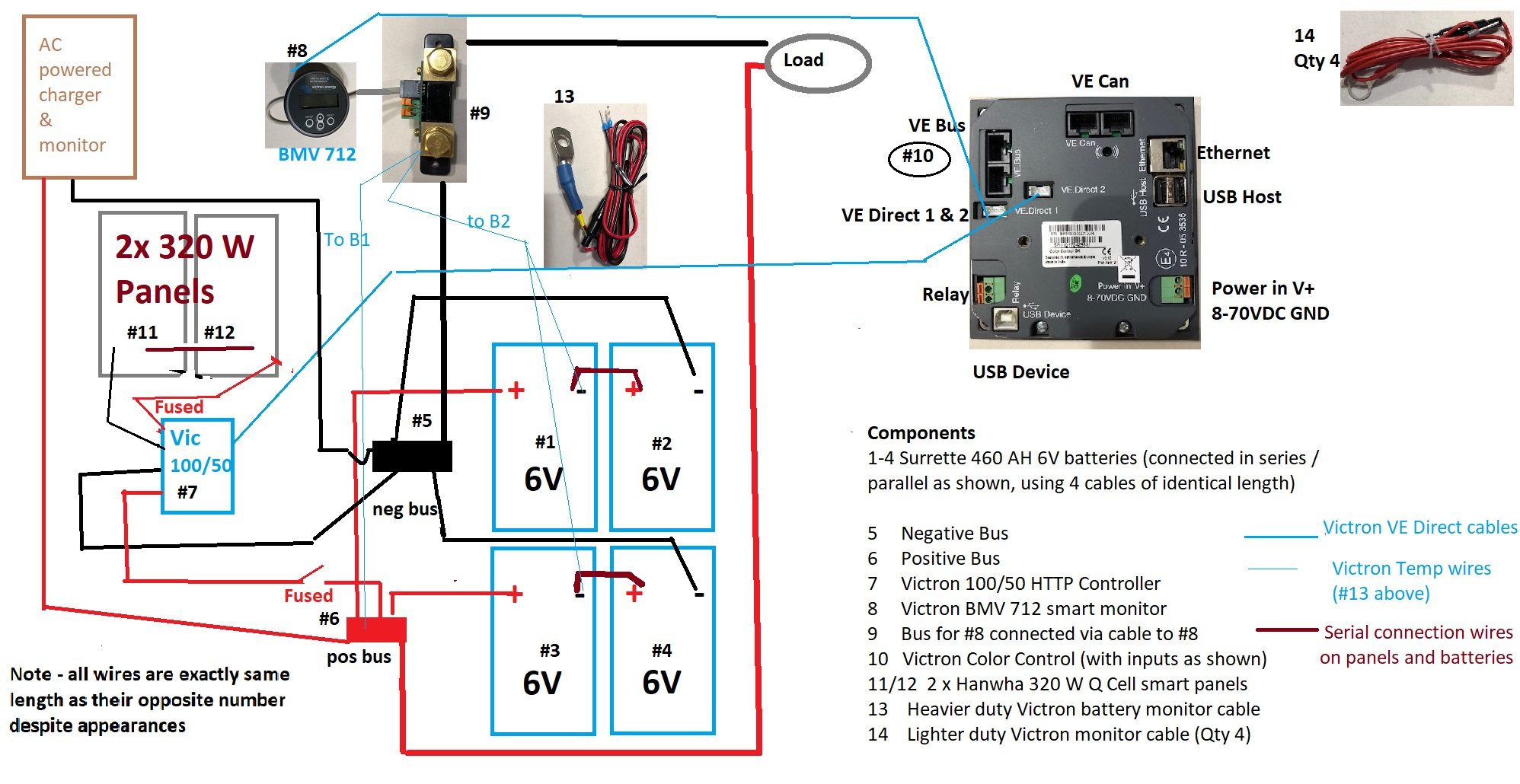
One very important detail here is that your negative bus needs to be on the "load" side of your shunt, not the battery side. All negatives, including chassis grounds, charge source negatives, etc. etc. need to run to the "load" side of the shunt so that the BMV can see what's going on.
So: both negative cables (but nothing else) from your battery run directly to the "battery" side of the shunt; then connect your negative bus to the "load" side of the shunt and connect all other negatives to the bus.
@Justin Cook I am confused in that the diagram provided by Victron specifically indicates that all negatives should be combined via exactly equal length cables to a shared bus, To be clear, there are no loads suggested to be connected to the bus. It goes batteries ->bus -> shunt -> a load bus at the wiring panel. Are you suggesting that the chargers should be connected after the shunt?
Secondly, the diagram shows the B1 cable connected to the positive battery bus (and thus to the batteries' POS connections) - also directly as shown in Victron's diagram. I'd be very grateful if you could help me understand where I am misunderstanding...
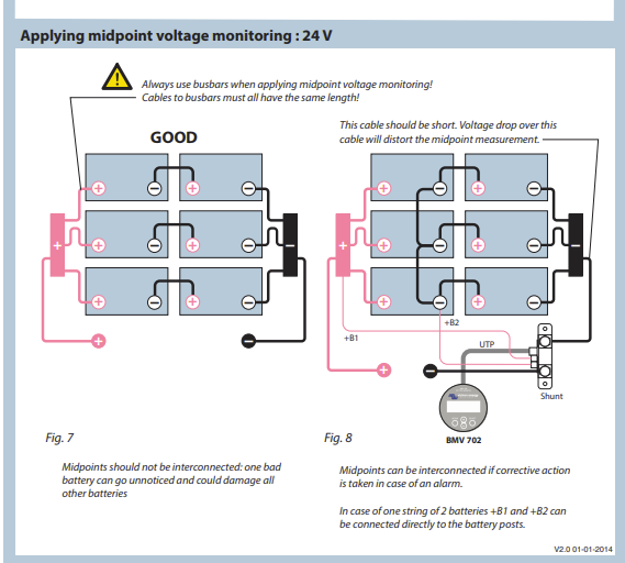
Your drawing appears to show your AC charger negative hooked up to the negative bus, as well as the MPPT negative, before your negative bus connects to the "battery" side of the shunt, thus why I was saying your drawing won't work. Victron's schematic is accurate in that all battery negatives should be combined at or before the shunt, but you show other negatives combined there as well, which is what will give you inaccurate readings.
The two wires that I've highlighted need to connect to the "load" side of the shunt.
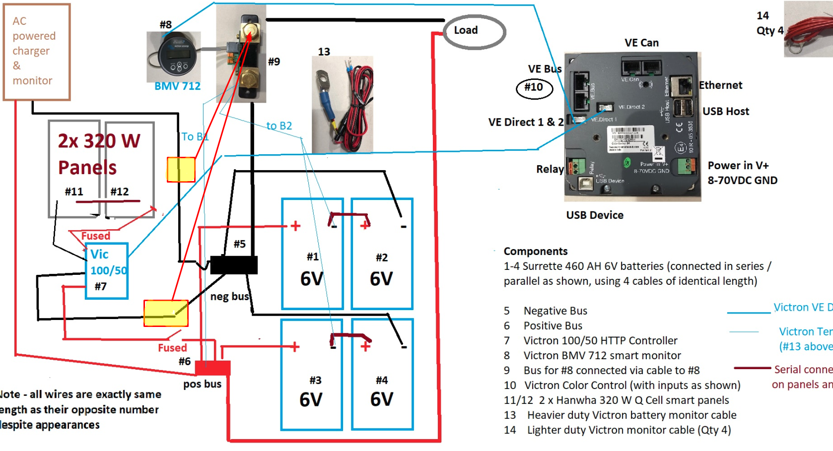
I may be confused because you're showing the schematic for midpoint voltage monitoring, which is correct, but you're proposing using a temperature sensor, which you are not showing the schematic for. Understand that you can't hook the temperature sensor up to the POS bus, it needs to be hooked up to the battery. Else you're just measuring the temperature of your bus.
In your opinion - and thanks for taking the time thus far - What should I monitor? To the extent it might matter... 4 virtually brand new AGM batteries. And then how to best configure those probes?
Well here's the thing... with the 702 or the 712, you get to have either temperature monitoring or mid-point voltage monitoring... you can't have both. For your application, and considering that the temperature sensor is designed for a single 12v battery rather than a 2x6v battery bank, I suggest that you abandon the use of the temp sensor and instead set up your BMV to use midpoint voltage monitoring; the temp sensor is designed to mount to a single 12v POS battery terminal and, since it also supplies power to the BMV's shunt PCB and monitor, I don't believe it would function if it was only hooked to a 6v battery. So abandon the temp sensor, hook up the BMV to monitor midpoint voltage.
If you're really concerned about the temperature of the batteries, I would recommend two Smart BatterySense modules that you would connect between each 2x6v battery bank. Then, if you wanted, you could set up a small VE.Smart Network between them and your MPPT (if it's a Smart model) or, keeping it simple, you could simply connect to them on your phone periodically to check your temperatures.
Also, if you use the temperature sensor for the BMV 712, the wires from the temperature sensor completely replace the single power wire for the shunt, so the wire you have currently marked "to B1" goes away; the temperature sensor connects to your positive battery terminal, not the negative, and you connect the red wire from the temperature sensor to B1 on the shunt and the black wire goes to B2. Please do not connect the temperature sensor the way you currently have it drawn; as it's currently shown it will fry your PCB and likely the temp sensor as well.
Possibly I am mistaken, but the picture shows the negative busbar connecting 2 battery negatives, the solar charger and the AC charge controller.
It appears that the monitor shunt is between the negative busbar and the load. As such, it will be monitoring the load drain but not the charging from the charge sources, unless the neg lines from the charge sources are connected to the shunt load side.
If you had a second neg black busbar wired to the load side of the shunt and moved the neg loads and charging sources to that shunt it would be more obvious that the single battery monitor is intended to monitor both charging & drain activities.
Thanks @Justin Cook!
Here is what I believe to be the correct revised diagram. If you would confirm I'd be very grateful. I'd also appreciate advice on the wire size I should use to connect the Neg terminals on batteries 1 and 3 to B2... It looks like the connections won't take much more than #18 - maybe less? That's all it takes? 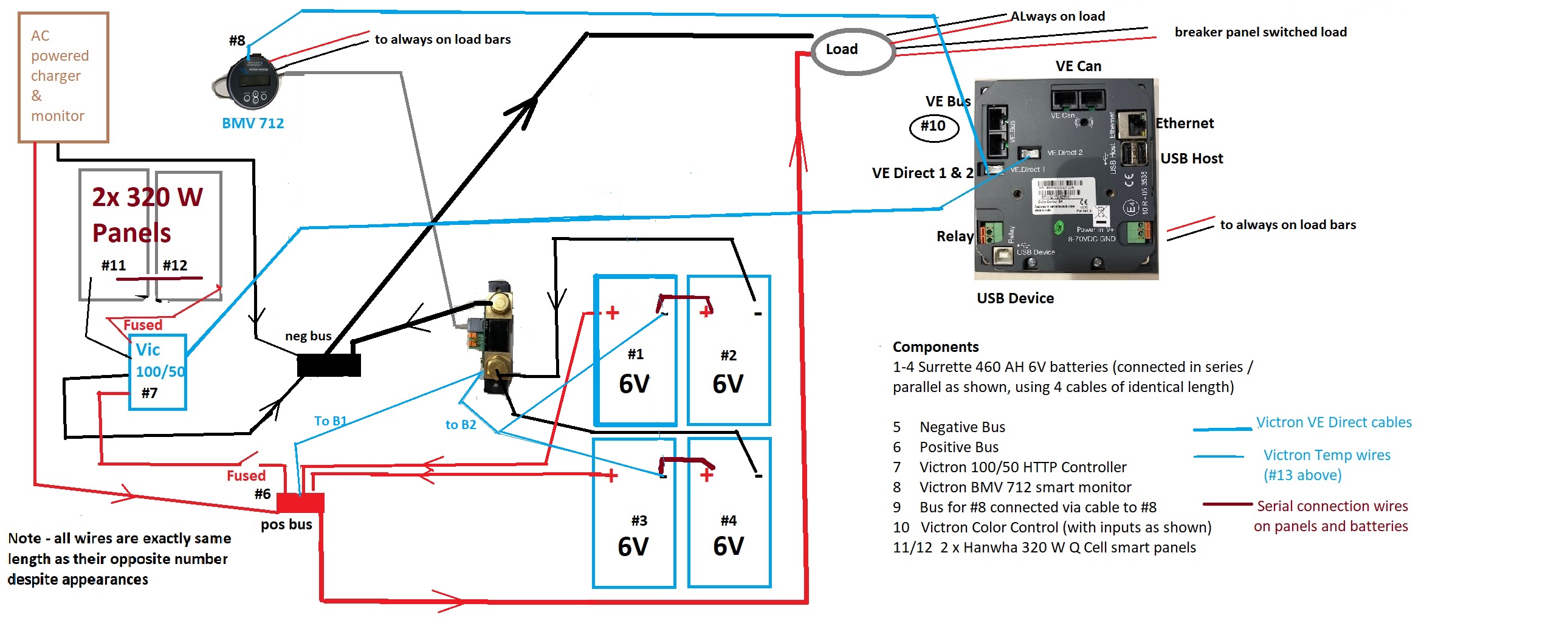
Weird... I swear I answered this before now but my replies have vanished... so, er, yes... as long as you're doing midpoint voltage reading, this is correct. I'm a little thrown off by the "Victron Temp wires" label, because if you're using the Victron temp sensor this is not the correct way to wire it.
If you're measuring midpoint voltage, then yes, this will work, and yes, #18 will do you fine. I recommend ferrule terminations at the shunt side, or at least dipping your ends in solder, to help you push the wires into the little spring clips without getting runaway strands.
If you're going to use a temp sensor, this wiring changes... confirm that you're abandoning the temp sensor?