question

Matthias Pallhuber avatar image
Matthias Pallhuber asked

Multiplus on 3 phase ESS with new inverter JK BMS - Ve.Bus State

I am running a 3 phase Multiplus 2 setup without MPPTs. I have a 16 cell Eve 280 ah battery attached to the system. PV inverters are connected to both AC in and AC out. The setup is controlled by the BMS which sets the CCL=190A and CVL=55.2. The new JK bms has also option to set a float voltage (53.6V) after an absorption time of 1 h in my case. The absorption time starts as soon as one cell hits the SOC = 100% limit of (3.45 V).

What i am experiencing is that my SOC 100% limit e.g. one cell has reached 3.45 V is triggered at low SOC. In the example below around 60%. I therefore tried to limit in ESS some parameters. I have set charge current limit to 80A and voltage limit in fact to (55.1 V). This did not really solve the problem.

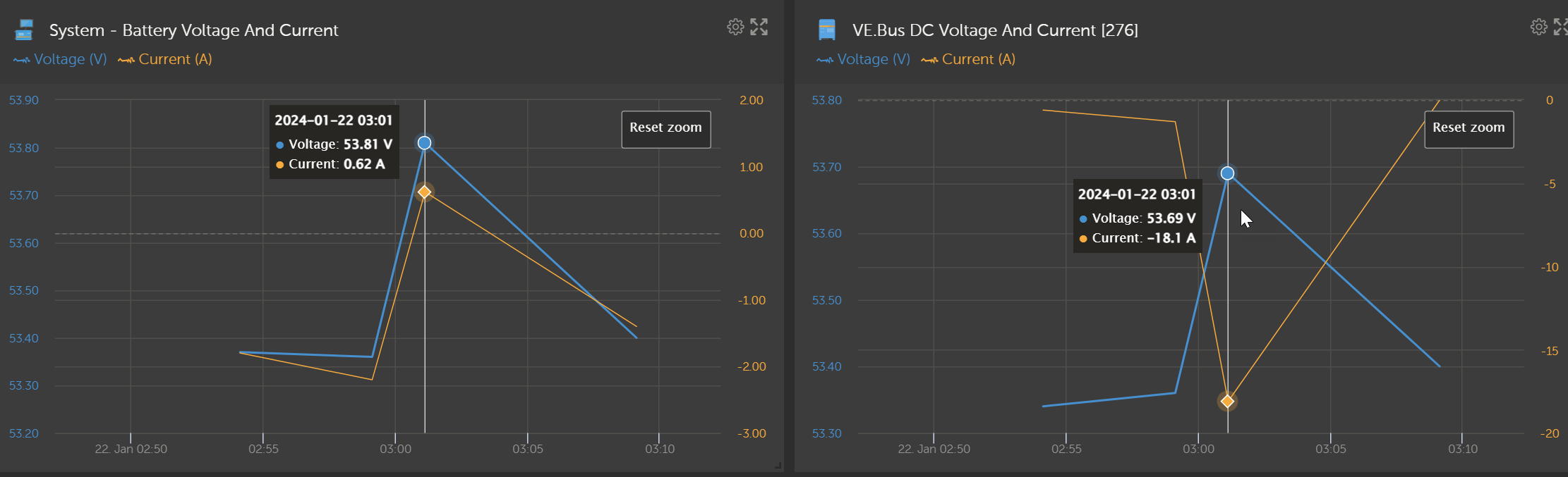
After monitoring the parameters i found a change in VE bus state to absorption at the point of time when the SOC was jumping

1706036401377.png


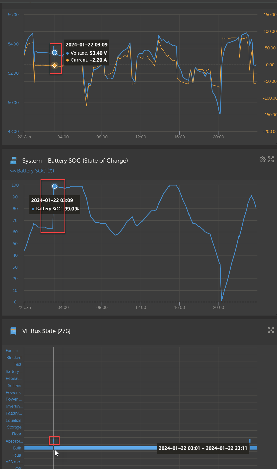
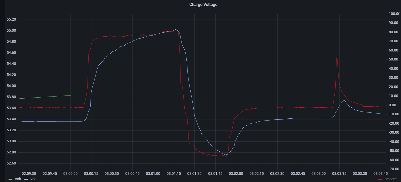
if you zoom into the time spot it looks like this: Starting at 03:01 it goes into absorption until it hits the 100% trigger voltage on cell level. After that charging stops.

1706036618075.png


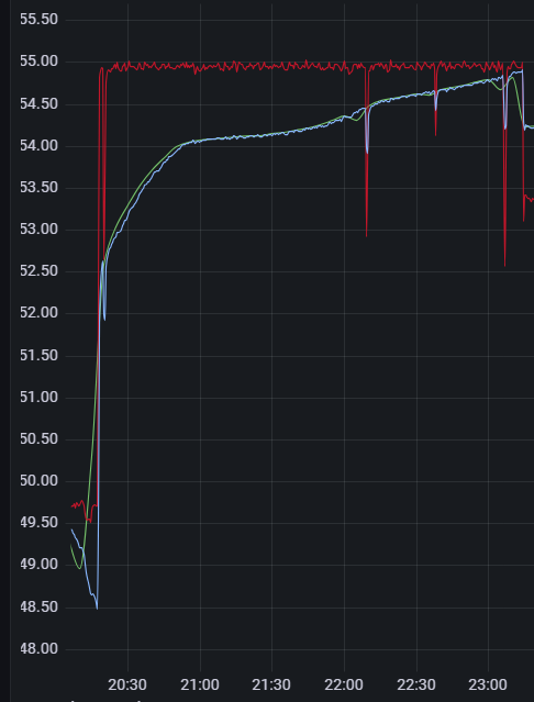
In order to understand my charging curve better i have been charging the battery from very low SOC with 80A to see if this is somehow due to a charge current of 80A and the battery not being able to cope with it. Beside some test which i did in between this is very smooth voltage increase from low to full. E.g. I could not reproduce the SOC jump in that case.

1706036881040.png


I try to get a better understanding whether I have correctly configured the system. What i am wondering is why the VE Bus State is changing to absorption and if this could be the root case for the steep voltage change and the 100% SOC jump. Should in the case of a BMS controlled system the Ve.Bus State change at all?

Can anyone help with this question?


SOCVE.Bus
1706036401377.png (217.4 KiB)
1706036618075.png (108.4 KiB)
1706036881040.png (51.8 KiB)
2 |3000

Up to 8 attachments (including images) can be used with a maximum of 190.8 MiB each and 286.6 MiB total.

3 Answers
prein avatar image
prein answered ·

Probably an out of balance battery pack. Can you show the voltage curve of the individual cells?

To solve it, you need to balance the individual cells. Slowly charge to 56 volts and Keep the pack above 56 volts for a day or so. After that it should be working better with the original settings

2 |3000

Up to 8 attachments (including images) can be used with a maximum of 190.8 MiB each and 286.6 MiB total.

prein avatar image
prein answered ·

Probably an out of balance battery pack. Can you show the voltage curve of the individual cells?

To solve it, you need to balance the individual cells. Slowly charge to 56 volts and Keep the pack above 56 volts for a day or so. After that it should be working better with the original settings.


I am assuming you have the jk bms with 2A active balancer. If not, you probably need an active balancer to solve the imbalance.

1 comment
2 |3000

Up to 8 attachments (including images) can be used with a maximum of 190.8 MiB each and 286.6 MiB total.

Matthias Pallhuber avatar image Matthias Pallhuber commented ·

Correct, it has a 2 A active balancer. 1706038294539.png
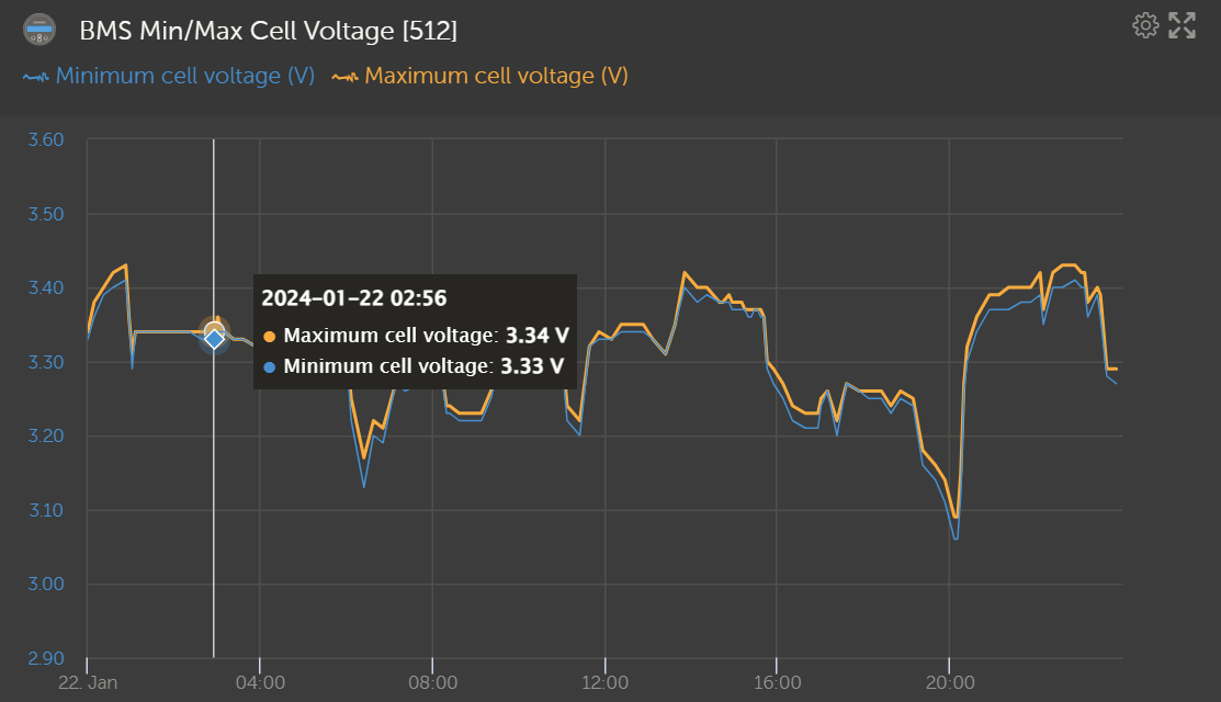
I think balancing at that specific point of time was pretty ok from what i would be able to judge out of statistics. I still dont understand why the charging volt would go from 3.33Vish to 3.45 V in a minute given the charge current is 80A. You can see that in the details chart from 3:00:15 to 3:01:15 e.g. in one minute it increases from 54V to 55.1 V on a constant 80A. That is why I am suspecting something else to happen:

1706038778293.png

Why would it increase charge voltage so rapidly? it should be able to push 80A into the battery without that high Voltage?

0 Likes 0 ·
1706038294539.png (85.5 KiB)
prein avatar image
prein answered ·

The bottom graph looks standard for a near full battery: charging starts with 80A. Battery voltage increases and when cells get full, the cell voltage increases. So nothing strange here. 3.45 V is not really that high.. It is often the balance start voltage. Meaning the battery, or at least 1 cell, is nearly full. So the multiplus is acting what it should : to protect overcharge stop charging.

The individual cell graphic looks unrelated. No rise in voltage visible. That's odd.. Should be able to see a rise from 3.3 to 3.45 there as well..


So: or a big imbalance

Or a misreading of pack voltage

Is the system bms controlled? So the voltage you see is the voltage measured at the bms? You can try to plot the voltage of the bms against the voltage of the ve.bus system. Maybe there's a loose connection somewhere (probably in the bms then)

2 comments
2 |3000

Up to 8 attachments (including images) can be used with a maximum of 190.8 MiB each and 286.6 MiB total.

Matthias Pallhuber avatar image Matthias Pallhuber commented ·

its BMS controlled. Yes the Voltage is coming from the BMS.

1706041936710.png

there is only minor differences but maybe also coming more from not very precise statistics.

For my understanding. Is the Ve Bus state. e.g moving to state absorption a consequence of a high voltage or is it rather the root cause of the high voltage? What I did not mention is that I have ESS set to optimized without battery life. Not sure if this makes a difference especially with a BMS controlled system.

0 Likes 0 ·
1706041936710.png (157.4 KiB)
prein avatar image prein Matthias Pallhuber commented ·
It's the consequence of the rising voltage. Ve state is following bms control. Bms tells that the battery is at 100% (and probably lower cc or cv setting. But that's not in the graph)


You miss infobecause of granularity of the data now. This graphs shows nothing going into the battery. So you should do another test.


Try charging to 100% with reduced amps and observe the changes. Hopefully you can observe a misbehavior or some misconfigured (bms) settings

1 Like 1 ·

Related Resources

What is VE.Bus?

Additional resources still need to be added for this topic