question

hello-world avatar image
hello-world asked

Correct wiring and setup for Orion-Tr Smart DC-DC charger with VE.Bus BMS V2

Hi there, Looking for some help on the 2 conflicting diagrams in the Orion-Tr smart user booklet.

I have 3 x 200Ah Victron Smart LiFePO4 batteries connected to a Quattro 2, utilising a VE.Bus BMS V2 for control (I have a Cerbo GX for monitoring) This is all fine charging from the grid and from 1700W solar via 2 x 100/30 Victron MPPT as one VE Direct cable from each MPPT to the Cerbo takes care of shutting down the charging from the Solar to protect the LiFePO4 batteries.

I do need however to be able to charge the lithium bank from the engines when running as an additional redundancy.

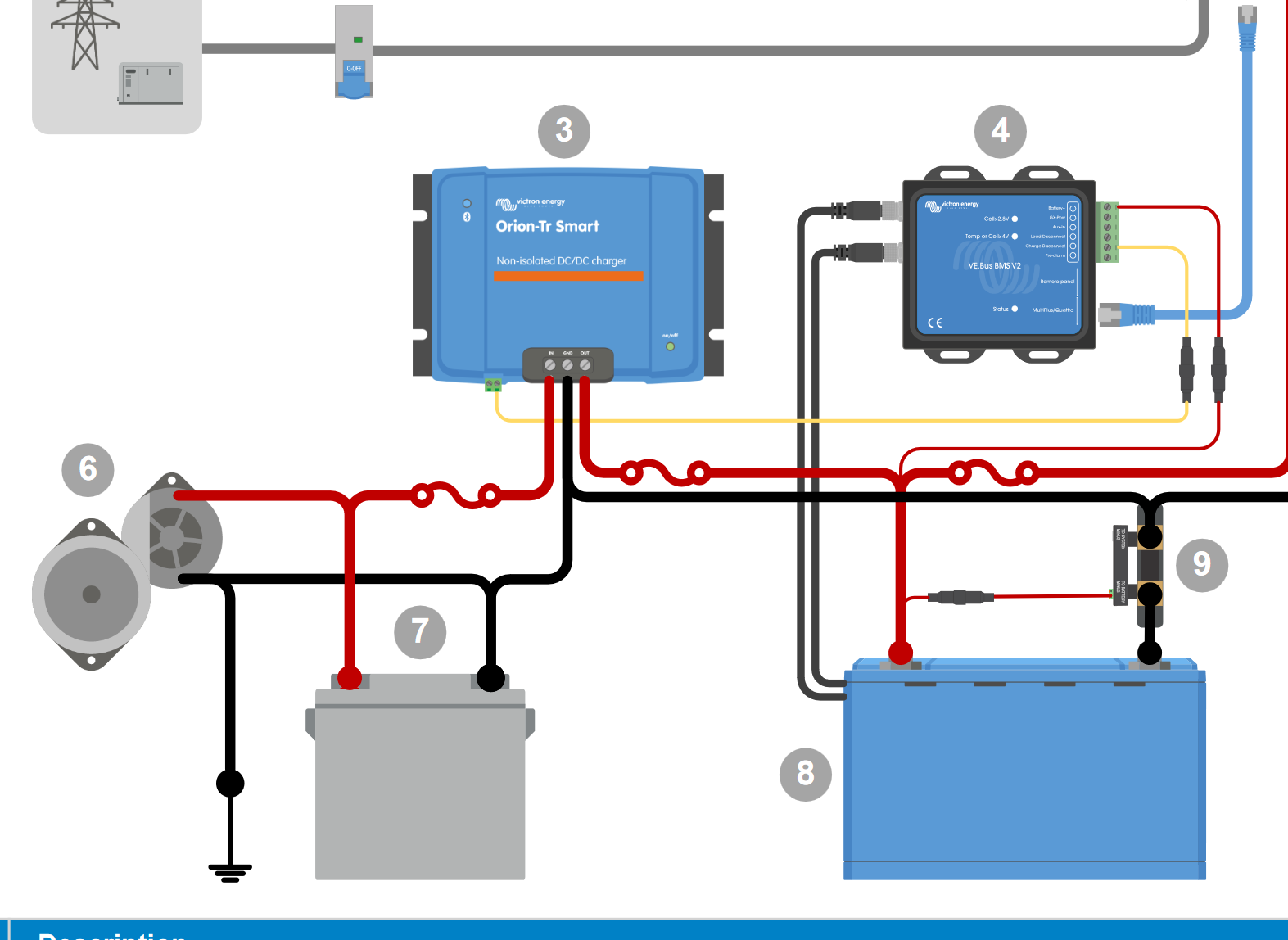
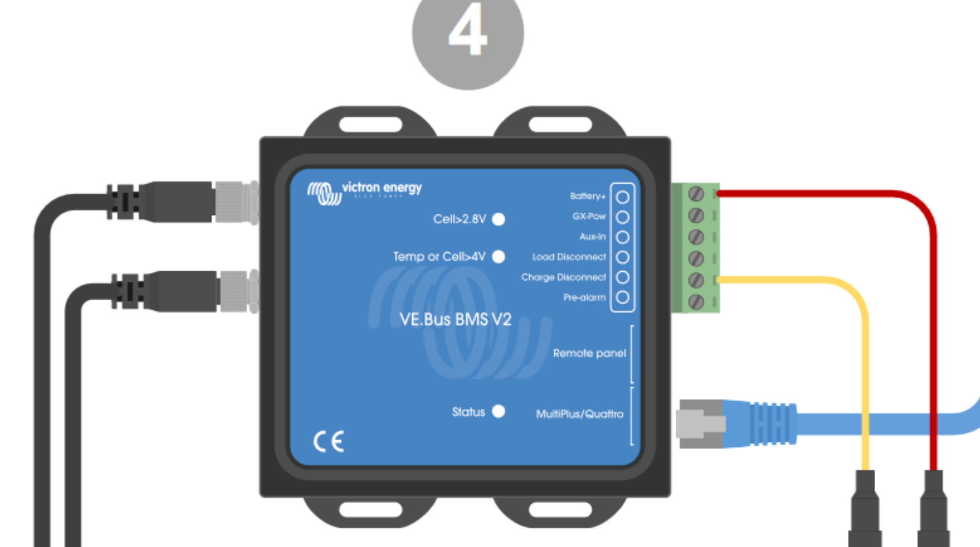
I have 4 x Orion Tr-Smart 12/24 - 15 units daisy chained together and need to connect this to the VE.Bus BMS V2 to enable charging shutdown for protection of the lithium.

I also need to enable the charging ONLY when the engines are running, when the alternators are producing power, but the VE.Bus BMS V2 can still shut the Orions down if required to protect the batteries.

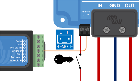
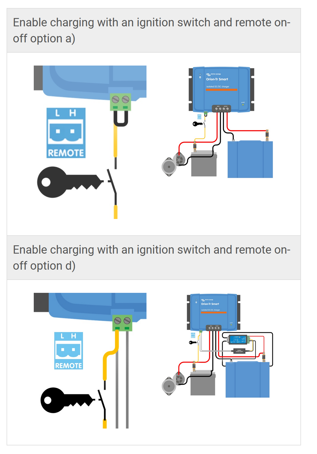
The 2 diagrams in the manual contradict each other, one showing L-Pin wiring connected with jumper to H-Pin with a yellow wire to ignition, I am told this will destroy the unit however....

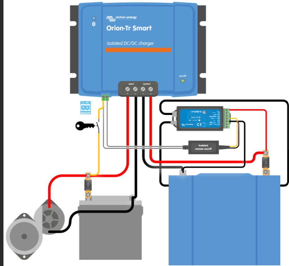
The other diagram is the H-pin which shows a live feed from the input via the ignition switch to the H-Pin. I can't find anything though that clarifies the VE.Bus BMS V2 wiring in conjunction with this.

Any advice much appreciated!!

BMSorion-tr smartsmart lithium
2 |3000

Up to 8 attachments (including images) can be used with a maximum of 190.8 MiB each and 286.6 MiB total.

7 Answers
grandalaskaexp avatar image
grandalaskaexp answered ·

Maybe post the pictures you're referencing. or the link. You might also want to look at the schematics on the product info page as well....But if I were going to send it, I would wire your BMS ATC, which says Charger to your H Pin on your DC2DC, and then wire your ignition to L. But I woud I recommend you continue to do your research. 16593c869cbd77.png


16593c869cbd77.png (36.9 KiB)
2 |3000

Up to 8 attachments (including images) can be used with a maximum of 190.8 MiB each and 286.6 MiB total.

hello-world avatar image
hello-world answered ·

Thanks for the reply.

This is one image from the VE.Bus BMS V2 manual

1705923152614.png

I can't add another image as all I get is "No link in upload response" very frustrating


1705923152614.png (176.7 KiB)
2 |3000

Up to 8 attachments (including images) can be used with a maximum of 190.8 MiB each and 286.6 MiB total.

hello-world avatar image
hello-world answered ·

picture1.png

This is the image from the Tr-Smart manual, but it seems to show only the VE.Bus BMS (with 2 wires) NOT the V2, that's where I can't find any clarity


picture1.png (385.7 KiB)
2 |3000

Up to 8 attachments (including images) can be used with a maximum of 190.8 MiB each and 286.6 MiB total.

djsmiley avatar image
djsmiley answered ·

Use the H+ port. If you're using a D+ switched signal and have the H+ already in use you can add a relay, or add a battery protect on the output of the Orion.

2 |3000

Up to 8 attachments (including images) can be used with a maximum of 190.8 MiB each and 286.6 MiB total.

klim8skeptic avatar image
klim8skeptic answered ·

@Hello World CONFIRM if you are using an isolated, or non isolated Orion TR Smart.

There are differences between the 2 units regarding remote port usage.

2 |3000

Up to 8 attachments (including images) can be used with a maximum of 190.8 MiB each and 286.6 MiB total.

hello-world avatar image
hello-world answered ·

@klim8skeptic using isolated Tr-Orion smart (4 x 12/24-15 daisy chained together to give 24VDC 60A output)

I was informed by the Victron dealer I bought the units from that the H terminal should be connected to the Charge disconnect from the VE.Bus BMS V2 which is what I have done, but they couldn't tell me exactly how I should wire the ignition side, as they have no experience of that (they don't do mobile stuff, more domestic?)

1 comment
2 |3000

Up to 8 attachments (including images) can be used with a maximum of 190.8 MiB each and 286.6 MiB total.

klim8skeptic avatar image klim8skeptic ♦ commented ·

@Hello World As per the Orion Smart isolated manual You can enable charge with an ignition + source and also enable charge from the BMS ATC signal via an Orion-Tr Isolated DC-DC Charger remote cable . The cable is required as there no ground connection between the start and aux batteries.

orion-isolated-remote.png

US Van manual and drawing shows this setup (minus the ignition enable).

As to whether you can bridge the battery grounds (and do without the special cable) together, dunno. Maybe ask a new question.

0 Likes 0 ·
hello-world avatar image
hello-world answered ·

Thanks for the reply, the image you added is exactly where I am struggling, it shows the BMS V1, which does require 2 cables with the isolated remote, whereas the VE.Bus BMS V2 doesn't have the 2 connection points, just a single line "charge disconnect" so you can't use the special cable as shown in the Isolated DC-DC manual.

1706093862548.png


1706093862548.png (285.3 KiB)
2 comments
2 |3000

Up to 8 attachments (including images) can be used with a maximum of 190.8 MiB each and 286.6 MiB total.

klim8skeptic avatar image klim8skeptic ♦ commented ·

@Hello World The VE Bus BMS v2 gets its ground (- battery) via the rj45 cable to the multi, and has no ground terminal as such.

The black wire from the https://www.victronenergy.com/cables/orion-tr_isolated_dc-dc_charger_remote_cable goes to the battery negative terminal, and the yellow wire goes to the charge disconnect terminal of the The VE Bus BMS v2.


0 Likes 0 ·
hello-world avatar image hello-world klim8skeptic ♦ commented ·

Thanks for the reply and sorry for the delayed response, been off-grid.

Can I just confirm "The black wire from the https://www.victronenergy.com/cables/orion-tr_isolated_dc-dc_charger_remote_cable goes to the battery negative terminal" in your response, means the battery negative terminal of the starter battery?

This will then ensure that the charge disconnect works correctly should the BMS require to shut down the DC-DC chargers due to a issue with the batteries etc?


0 Likes 0 ·