question

Bert avatar image
Bert asked

How to account for more than one SmartShunt in Cerbo

This is how my installation looks like:
2 Banks of 16 Cells LifePo 230 Ah (48V/230  Ah each)
Each bank with a JK BMS for over/undervoltage cut-out and active balancing, works perfectly well.
Each bank with a Smart-Shunt Monitor, works well and shows „real“ data over Bluetooth.
3 units of MPTT 150/45, each of them with their separate string of 4* 410 Wp
The three MPTTs work in parallel for charging – works perfectly well.
1 Cerbo GX, collecting the data of 3 * MPTT (via Direct.VE) and 2 * Smart-Shunt (via USB)
All expected devices show in the Cerbo device list.
Charging power (PV) will be correctly added up from the three MPTTs.
Here is the problem:
Of the two Smart-Shunts,only the data of one will show in the battery charging/discharging.
The data shown in the dashboard shows more or less exacly 50% of what goes in/out the batteries.
How can I teach the Cerbo to add the data from the two Smart-Shunts?

Below some screen shots:
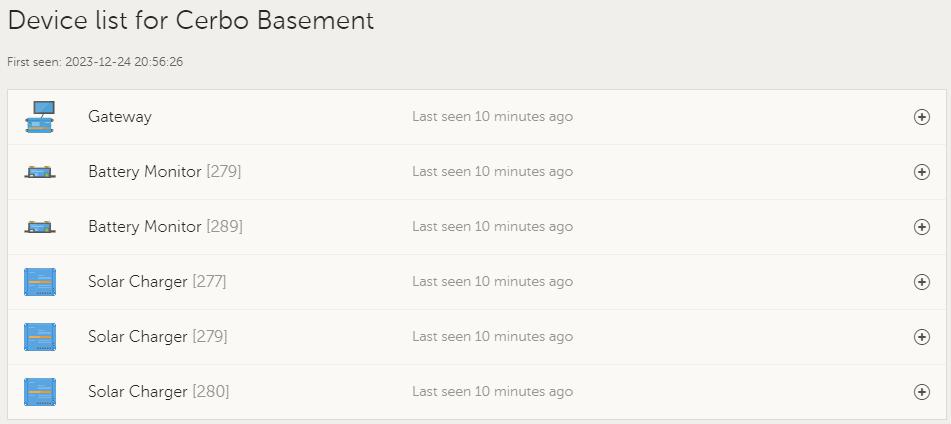
Cerbo Device List - showing all expected devices

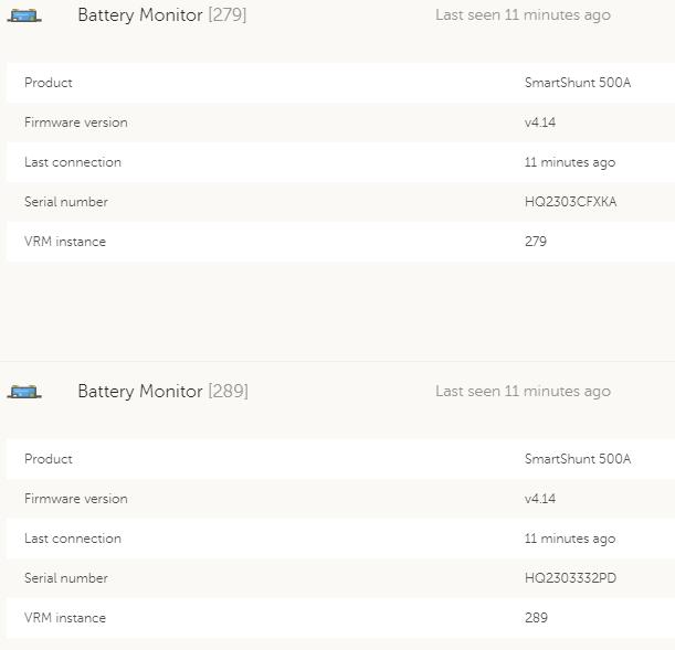
Cerbo Device Details for SmartShunts - ok

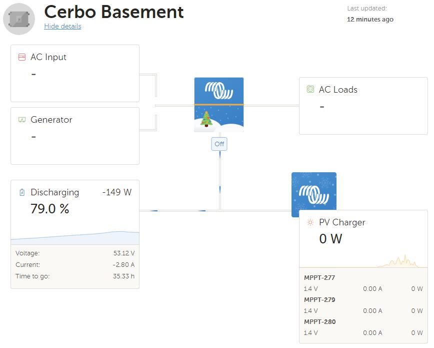
Cerbo Dashboard: shows Discharge of -149 W. I know for sure that my hose ran at approx 300 W at that time, confirmed by the current readings of the two JK BMSses.

Thanks for any suggestions.cerbo-gx-deviec-list.jpg

cerbo-gx-smartshunt-detail.jpg

cerbo-gx-dashboard.jpg

cerbo gxSmartShunt
2 |3000

Up to 8 attachments (including images) can be used with a maximum of 190.8 MiB each and 286.6 MiB total.

3 Answers
matt1309 avatar image
matt1309 answered ·

Hi @Bert


Why use 2 smart shunts and not just one? I have the exact same setup but using one smart shunt. If you're desperate for individual battery data what i'd personaly do is add JK BMS custom driver so they can communicate with victron system but still use a single smart shunt to monitor the overall battery. That way you've got best of both, segregation of duties between bms and smart shunt and also have the individual battery data.


The other option is a battery aggregator custom driver but to me that feels more messy.

2 |3000

Up to 8 attachments (including images) can be used with a maximum of 190.8 MiB each and 286.6 MiB total.

Bert avatar image
Bert answered ·

Hi Matt

Thanks for your comment.

Why not use a single SmartShunt - fair question :-)

I want to have my BMSses and SmartShunts veeery close to their batteries...

Thwo BMSses (JK) are necessary because the banks are in parallel on a bank level, not cell level. Thus for using the balancer of the JK BMS, I am using two of them.

Using a single SmartShunt, I would end up with some 0.3 m of cable from the battery minus, arriving at the SmartShunt. Doable, but not what I would favour....

The reason I have SmartShunts at all is to avoid any software/drive development in the first place....(have done so 25+ years in my professional career, now I'm happy to "play" on the Arduino with my son).

Thanks again

Bert


1 comment
2 |3000

Up to 8 attachments (including images) can be used with a maximum of 190.8 MiB each and 286.6 MiB total.

matt1309 avatar image matt1309 commented ·

Hi @Bert Yeh same parallel at a bank level.

I have same setup but I just put my smart shunt equidistance from each pack.

Definitely the easier solution in my opinion.

What @Justin Cook is right but what you can essentially do is aggregreate them by making a virtual battery (victron gives decent documentation on custom drivers) tldr here's some useful links:

The examples are in python but pretty sure they have c/c++ libraries if that's more your thing.

https://github.com/victronenergy/venus/wiki/howto-add-a-driver-to-Venus

Someone has made a virtual battery but you populate then populate the data using node red which probably adds latency. However there's no reason why you couldn't read each smart shunts data via dbus in the python driver to populate the values and loop to save some time if you want.

https://github.com/arrow1800/Victron-VirtualBattery


Victrons generic example probably more appropriate if you're not going node red route.

https://github.com/victronenergy/velib_python/blob/master/dbusdummyservice.py


Some useful dbus path info:

https://github.com/victronenergy/venus/wiki/dbus#battery


A more complete example of energy meter. This is slightly different as data comes from the meters http api but this example at least shows populating values to dbus paths:

https://github.com/fabian-lauer/dbus-shelly-3em-smartmeter/blob/main/dbus-shelly-3em-smartmeter.py


I've only ever added custom tank sensor driver and updated via mqtt similar to virtual battery guys planned approach but Im pretty sure it's doable. If youre a dabhand with python then it might be easy for you. Definitely a mamoth task for me but hopefully the resources help.

0 Likes 0 ·
Justin Cook avatar image
Justin Cook answered ·

The system can only use and display 1 battery monitor for system SOC and other information; you can certainly toggle between the two that you have in the settings, or view the information from both in the device list and average the two yourself, but the Cerbo can only display 1 on the main screen.

2 |3000

Up to 8 attachments (including images) can be used with a maximum of 190.8 MiB each and 286.6 MiB total.