question

ako avatar image
ako asked

Strange Shunt behavior

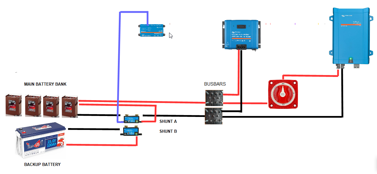
Can anyone explaine the folowing seemingly impossible behavior . When i connect the Backup battery to shunt B the voltage in the Main AGM batteries rises although theres no connection between them .

The main batteries were charging normaly in Absorption at 28.8 volts but as soon as i conected the Backup Battery the voltage in the Min Bank increased almost imediatly , i dissconected at 31.5 Volts to protect the AGMs .

The voltage rise was noticed first on the Victron connect then confirmed with a multimeter directly on the AGMs terminals . I dont know how far it would have gone uo and theres no way to find out without risking damage to them .


Opinions would be very much appreciated .

screenhunter-235.png

SmartShunt
screenhunter-235.png (184.0 KiB)
2 |3000

Up to 8 attachments (including images) can be used with a maximum of 190.8 MiB each and 286.6 MiB total.

6 Answers
kevgermany avatar image
kevgermany answered ·

Have you tried a common earth between them? First guess is that there's an earth voltage difference causing your problem.

2 |3000

Up to 8 attachments (including images) can be used with a maximum of 190.8 MiB each and 286.6 MiB total.

ako avatar image
ako answered ·

The circuit is exactly as in the diagram Kevin , its because theres nothing common between them and the backup battery is a totaly closed circuit that makes it seemingly imposible . Both the shunts have Bluetooth and the Cerbo had always had DVCC turned on to take Voltage Temperature and Current datea from Shunt A but i cant see how any or that could be responsible .

2 |3000

Up to 8 attachments (including images) can be used with a maximum of 190.8 MiB each and 286.6 MiB total.

JohnC avatar image
JohnC answered ·

@AKO

If you have Smart networking enabled somewhere then the mppt may be controlling off battery B. The Cerbo/DVCC won't use bt to receive data or push it anywhere. Your diagram isn't great because it doesn't show your control wiring to Cerbo and elsewhere. So we can't see what you really have connected by wire or bt.

Don't expect to use both together successfully.


2 |3000

Up to 8 attachments (including images) can be used with a maximum of 190.8 MiB each and 286.6 MiB total.

ako avatar image
ako answered ·

I read that you cant use Smart Networking and VD together John so opted just for VD and everything has VD cables . Nothing else connected to Cerbo other than what is shown in the diagram except for the Temperature cable between Shunt A and Main Batteries , not even fuses or other switches. .

Tried this morning while MPPT was in Bulk charge and Backup battery didnt effect anything then , will try later when in Absorption and then Float and see if i can find some other pointers .

1 comment
2 |3000

Up to 8 attachments (including images) can be used with a maximum of 190.8 MiB each and 286.6 MiB total.

JohnC avatar image JohnC ♦ commented ·

@AKO

Another thing that may cause a rise in Vabs is Temp Comp. Watch the end result on VRM Dashboard (with Show Details ticked). There was an issue for some users a while back where T was showing unusually low and causing issues.

Please be precise with your quoted readings. Like the 28.8V you mentioned before isn't actually normal with TC in play.

2 Likes 2 ·
ako avatar image
ako answered ·

I can now reproduce the issue although it doesn't help me or even explain why its happening . I found that if the VE cable for Shunt B is plugged into the number the number 3 port on the Cerbo that the problem is there , in fact if i plug the MPPT into it the voltage shown on it with Victron Direct also rises . I am wondering if it has anything t do with the fact that i have 2 sets of batteries and 2 shunts and my Cerbo has DVCC activated wich raises anther question , how does the Cerbo know which Shunt to take the data from to pas on if there's more then one . Another point i am unsure of is that while i can see its useful to know the voltage and temperature of the batteries as measured by the shunt for controling charging i dont understand what shared Current is and why would that be useful for anther piece of equipment to know it .

1 comment
2 |3000

Up to 8 attachments (including images) can be used with a maximum of 190.8 MiB each and 286.6 MiB total.

JohnC avatar image JohnC ♦ commented ·
@AKO

The Cerbo DVCC will use the shunt designated as a Battery Monitor. With 2x set to that, then who knows? Probably the underlying reason for your issues. Set the other to something else.

DVCC's shared Current (SCS) is particularly useful for terminating Absorb stage in mppts using the mppt Tail function. With Pb batts, far better IMO than Fixed or Adaptive modes.

0 Likes 0 ·
ako avatar image
ako answered ·

Thanks John , i think you are right and having 2 shunts is the cause of the problem but i dont see anything anywhere to say you cant have miore than one, in fact read a lot where more than one is used without issue . Thank you also for the explination for Current , i agree also that it has to be better than Adaptive Asorbtion times which i find is often a mile out because it doesnt compensate for sudden high loads that give a missleading reading for a very short time causing the MPPT to stay in asorption longer thinking the batteries DOD had been much greater than it had , more of an issue on a smaller battery bank . Looks like i wil now have to see if theres some way to tell the Cerbo which of my two shunts to use for DVCC to eliminate this problem . I have renamed the Shunts so i know which is which sometimes but other times they are not shown by their custom name just their generic name which complicates things further .

2 |3000

Up to 8 attachments (including images) can be used with a maximum of 190.8 MiB each and 286.6 MiB total.