question

kurs270 avatar image
kurs270 asked

DVCC, Smart Shunt and ground potential(s)

On my Boat, I have a quattro and a cerbo. I am just on my way to remove the old (domestic) lead batteries and replace them with LiFePos.

The quattro's negative line is (obviously) connected to boat ground as is the starter battery and the engine.

In order to enable the LiFePos to limit charge current (i.e. in case of imbalance) I want to activate DVCC. The LiFePos are already "talking" to the cerbo, so everything is fine on that side.

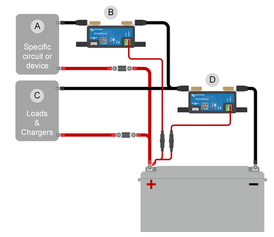
BUT: Other posts say (and that is also my experience) that DVCC only works correctly when the current going into or coming out of the DC system (i.e. all DC consumers and chargers apart from the quattro) is being measured by a SmartShunt configured as a DC meter.

The SmartShunt, however, normally has to be inserted into the negative line, thus creating a second ground potential which is at most 50mV above or below system ground. (depending on charging or discharging the batteries via the DC system)

In order for this to work correctly (and safely) there must be no other interconnections between the negative DC line and the boats ground, which cannot be guaranteed, especially not on a used boat with complex electrical installations.

In the best case, such interconnections would only lead to wrong measurements. In the worst case, hundreds of amps of current would happyly flow through a thin wire causing lots of unhappiness to my insurance.

So how should I wire this?

Would it be an option to insert the SmartShunt into the positive line, feeding SmartShunts supply from the 24V system which is also present on my boat? How about the SmartShunts VE.direct port? Is that galvanically isolated?

MultiPlus Quattro Inverter ChargerSmartShuntDVCCGrounding
2 |3000

Up to 8 attachments (including images) can be used with a maximum of 190.8 MiB each and 286.6 MiB total.

2 Answers
JohnC avatar image
JohnC answered ·

@Kurs270

I'm a little confused by your question, so bear with me.

If what you want the shunt to do is measure current to/from your house battery, then it's wired directly to the battery -ve. And everything else, charge, loads and GROUNDS are connected to the LOAD side of the shunt.

This may not suit where you want to mount it, but you'll need to deal with that. Think of it as a piece of calibrated wire, possibly even with less resistance than your ground wire.

I can't speak for the the VE.Direct cable, but I would expect it to be isolated. You could check it if you need.

I'm no fan of 'earth-return' systems on boats. Can be hard to avoid with engines, but the 48V system on my boat is all wire, no ground at all.


2 |3000

Up to 8 attachments (including images) can be used with a maximum of 190.8 MiB each and 286.6 MiB total.

kurs270 avatar image
kurs270 answered ·


I am talking about this configuration, taken from the SmartShunt manual, Chapter 3.7. "Wiring for use as DC meter"

My question is about Shunt "B" and the resulting difference in potential between "A-B" and "C-D". The latter is what i have been referring to as "boat ground".

Of course there is no "earth return" on our boat - it is made of GRP. Anyway, it is not always obvious which minus wire goes where and I am afraid the stray currents resulting from unwanted interconnections between the 2 "minus"-rails may lead to all kinds of trouble.

1701176096559.png


1701176096559.png (64.0 KiB)
3 comments
2 |3000

Up to 8 attachments (including images) can be used with a maximum of 190.8 MiB each and 286.6 MiB total.

JohnC avatar image JohnC ♦ commented ·

@Kurs270

Ok, I get the scenario. But I'm still tossed by your concerns.

You've mentioned "In the worst case, hundreds of amps of current would happyly flow through a thin wire". There may well be high currents through the main cables, but they should be sized for it. The only 'thin wires' in the pic are those to the shunt pcb, and they're fused (1A, but some got out there with 100mA fuses).

To use DVCC to pass across battery current to your chargers you'd use a shunt in 'D' position, designated as a Battery Monitor, and selected in the SCS component of DVCC as the current source for your chargers to work from.

Anything that happens on the LOAD side of D Shunt is irrelevant. A shunt in B position you wouldn't select as a DVCC source.


1 Like 1 ·
kurs270 avatar image kurs270 JohnC ♦ commented ·

Ok, that one now really leaves me puzzled.

in https://community.victronenergy.com/questions/235929/dvcc-not-controlling-chargerqattro-correctly.html

I described how, even though all voltages and currents (including the "DC system") were displayed correctly on the cerbo main screen, the DC loads are not taken into account when it comes to limiting the charge current. I did a very detailed description there, including the relevant topics on the DBus.

The first question asked by Alexandra was "Is your DC load measured? Or guestimates?".

When I answered that the DC load is estimated (rather correctly) as being battery current minus quattro current, nobody answered any more.

My bms is selected as "controlling bms" in the dvcc setup and "has dc system" is set to yes.

The Shunt in "D" position would be completely redundant in that setup since the battery current is already measured by the bms and correctly reported to and displayed by the cerbo.

Doing more internet research revealed that it is necessary to have a smart shunt measuring the DC loads and sources ( aka "DC System" ) in order for DVCC to take them into account when adjusting the charge current limit. That's what the shunt in position "B" is for.

---------

Regarding the "thin wires": No, of course they are not depicted in the above picture. But, for example, any non isolated data connection between a device powered from the "A" power domain and one powered from the "C" power domain would make up such a "thin wire", carrying unwanted stray currents.

I know in a perfect installation such connections shouldn't exist but this is a large boat with a rather complex electrical and electronical installation and I cannot guarantee that the whole installation is "clean" in this respect. A shunt in the positive line would help since it would not introduce an extra voltage difference between negative lines.

0 Likes 0 ·
JohnC avatar image JohnC ♦ kurs270 commented ·
@Kurs270

The plot deepens. So you have an unspecified BMS that you expect to measure battery current itself, then add on external dc loads to give your chargers a value to produce. This is beyond my pay grade.

The 'Has DC System' slider in the GX Remote Console (with no shunt) is just a by-difference calculation that gets it's own tile and a widget for Watts. It's useful for a broad view, but you wouldn't use it for control even if you could (I don't know, but expect you can't).

Sorry, but I can't help more with this. Maybe someone else has seen such?..


0 Likes 0 ·