Hello,
This was originally posted in the “modifications” space, but I then thought it was in the wrong place to get answered so I reposted it in this space and deleted the other. My apologies if it was incorrect but I am new to this forum and learning my way around.
As background, I am attempting to upgrade my m/h to lithium batteries. There is no solar at this time, so I would like to only install the necessary components needed now and will expand and add on later.
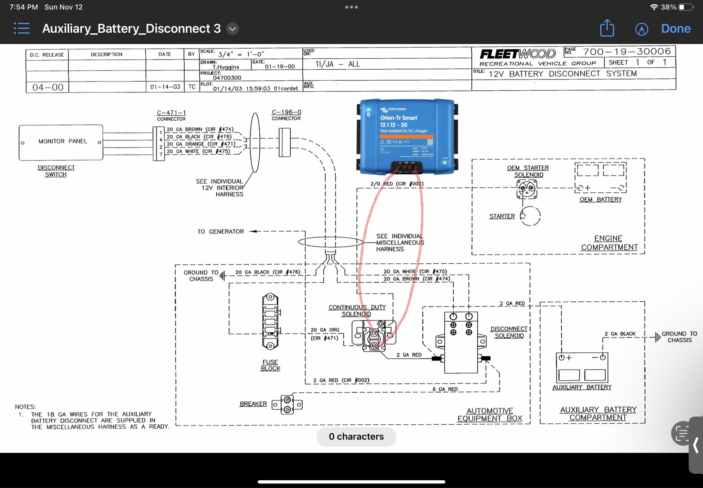
Currently the cabin has two 6v deep cycle lead acid batteries wired in series and looks to be charged by shore/generator power into a converter/charger. The batteries are also charged from the alternator when the vehicle engine is running (see “disconnect” schematic attached). There is an “emergency start” switch on the dash that you hold down to use the cabin batteries to jump the starter battery f needed (see “wiring” schematic attached).
All of the solenoids and relays are located in the auxiliary battery compartment in the cabin’s entry step. I know the new dc-dc charger needs to be installed as close to the auxiliary (house) batteries as possible, but I am still unclear as to where in the routing it should be inserted. On the schematic it appears the routing is the starter battery to a starter solenoid, to a “continuous duty solenoid,“ to a “disconnect solenoid,” to the auxiliary (house) batteries.
In one forum that I posted the question to, I was told no changes were needed to the current routing and to simply wire the charger in parallel with the “continuous duty solenoid” and that it would protect the alternator and maintain the starter battery jump option (Shown on “disconnect” schematic attached).
But in another forum I read that there was no way to maintain the jump option with lithium batteries and wiring the charger in parallel would bypass the charger’s output control, putting the alternator at risk. So I figured it would be best to get the information straight from the horse’s mouth.
Here are my questions and concerns:
1) In my situation, is the charger installed IN ADDITION TO all the existing solenoids, relays and wiring. If yes, at what specific location in the routing is it to be inserted for proper operation?
2) Or is the charger installed to REPLACE one of the existing solenoids or relays in the routing? If yes, which component/s need to be disconnected/bypassed/removed, and again please advise at what specific location in the routing it should be inserted?
3) For my better understanding and clarification, does the dc-dc charger allow bi-directional current that would allow the auxiliary (house) batteries to jump the starter battery if needed? If no, what, if any, benefit would be gained by wiring it in parallel with the “continuous duty solenoid?” Is there an alternative Victron component that would allow this scenario and add to my wish list?
4) I purchased the isolated 12/12 30a charger, but I believe the non-isolated version could be used. Are there any issues in using the isolated version anyway? If no issues, how would I handle the negative in & out ports?
All responses and advice would greatly be appreciated. Thank you in advance.