question

Jona Aal avatar image
Jona Aal asked

Pylontech batteries not charging from MPPT

HI All,

Posting this after looking extensively on the forum and contacting Pylontech direct, to no avail.

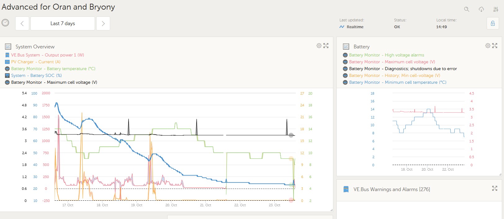
I have a system that is failing to charge the batteries from 23% SOC when the PV array should be giving c.2-3kW and daily production should be of order 8-10kWh.

System is Multiplus 2 48/5000, Cerbo GX, 250/100MPPT, Pylontech USC3000 x4

All the CANbus cabling has been installed a while and was working fine until last week. No obvious issues like mice etc. connections seem fine in VRM and through the cerbo screen onsite.

We had a generator set up until last week but that is currently away for repairs and unavailable until next week. COld weather is approaching so need to get this up and running asap.

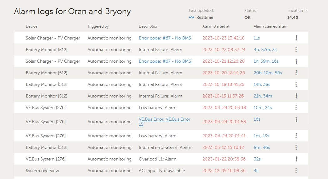
Multiple alarms, some common (Internal Battery Failure) others not so much (codes for the MPPT and BMS hgave only recently appeared).

Updated the MPPT firmware today as per a suggestion on this forum, reset the BMS control, asn per another suggestion. Neither has worked although I did see a change in the PV production up to 20W shortly after I did the updates. Also switching a larger load on seemed to kick the MPPT into action momentarily.

Battery is above 5 degrees so should take charge, there is a 230V heater that keeps them above 7 degrees but that is not going to be an option for much longer unless we get the PV working!

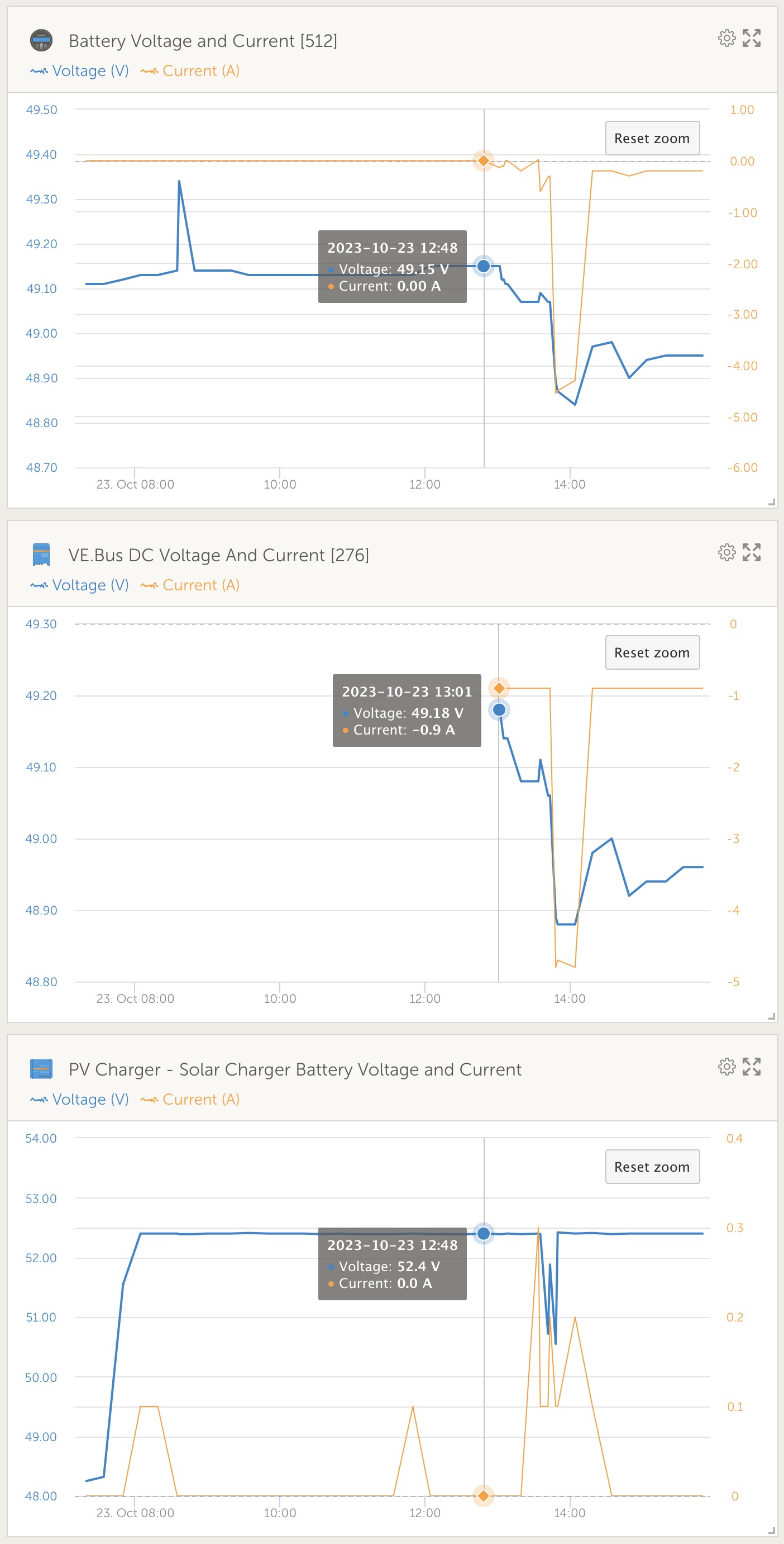
There is a discrepancy between the battery voltage reported via the Cerbo/VRM (c.49V) and that reported by the MPPT through victronconnet locally vie bluetooth (c.52V).

If any victron staff want to have a look that would be amazing @Guy Stewart (Victron Community Manager) @mvader (Victron Energy) the VRM Instance is: 48e7da89496f Images attached below

Many thanks,

Jonascreenshot-2023-10-23-144924.jpgscreenshot-2023-10-23-144655.jpg

MPPT Controllersbattery chargingBMSPylontech
2 |3000

Up to 8 attachments (including images) can be used with a maximum of 190.8 MiB each and 286.6 MiB total.

6 Answers
Guy Stewart (Victron Community Manager) avatar image
Guy Stewart (Victron Community Manager) answered ·

Hi @Jona Aal,

I had a quick look at your VRM site and the first thing I saw was that the DC voltage at the MPPT does not match the DC voltage at the battery.


The most common cause of this would be a blown fuse, or loose connection somewhere along the DC bus. That is where I would start my investigation.

cleanshot-2023-10-24-at-015828.jpg


2 |3000

Up to 8 attachments (including images) can be used with a maximum of 190.8 MiB each and 286.6 MiB total.

Alexandra avatar image
Alexandra answered ·

@Jona Aal

Ideally the person who installed should be troubleshooting.

Failing that local boots on the ground will be needed. Google victron where to buy and use your location.

An internal faliure is a pylontec problem. Not a Victron problem. Nothing can be helped there from this side. You will need to figure out which one has the issue and (possibly) remove it. But start with swapping which on is the master.

You can swap who is the master on the pylon stack.

Switch off battery life.

I assume by the mention of the generator that you are off-grid? One thing I have seen is keeping them charged can solve the internal error message. Might be awkward if you are off-grid.

The other option is to remove battery Comms from the system, try seeing if it wakes up then.

The other thing I have seen is the Comms cable, so a simple one. One way is to only connect the can h l and ground (so only 3 wires). Pins 1 to 3 should be empty, you get funny issues of they are not on the premade cables.

2 |3000

Up to 8 attachments (including images) can be used with a maximum of 190.8 MiB each and 286.6 MiB total.

Jona Aal avatar image
Jona Aal answered ·

Thanks @Guy Stewart (Victron Community Manager) I'll go and check the DC bus and fuses and take it from there..My initial fault finding has been batteries and BMS snce those are the alarms i've had. I have only had a small amount of time on site, with no tools so will go back and pull it apart bit by bit.

Also @Alexandra thanks for the suggestions. I am the installer so am doing the troubleshooting (!) I have been pretty thorough in checking cables are OK. I hav'nt managed to get any of the internal faults to be repeatable though they are frequent.

I'm sure thet keeping everything charged fully would be nice and over the last year that seems to have kept the internal fault issue at bay (we had it a lot after comissioning), off grid though you kind of need the batteries to be cycled!

The system is all on OEM cables, no mods and it has suddenly started behaving like this with no obvious cause. Pylontech are not particularly helpful and there is no foum dedicated to their batteries, so this forum is the only place where there is any level of experience.


Will post back with results.


Thanks again for your help


JOna

1 comment
2 |3000

Up to 8 attachments (including images) can be used with a maximum of 190.8 MiB each and 286.6 MiB total.

Alexandra avatar image Alexandra ♦ commented ·
No the pylon support is lacking a bit.

Find the intermittent is a pain so I hear you there.

Will be keen to hear the results.

0 Likes 0 ·
snoobler avatar image
snoobler answered ·

This exact issue with almost a 3V difference (MPPT was 3V higher than all other devices) has been demonstrated on this site by a user in Peru. Your configuration is nearly identical to his.

https://community.victronenergy.com/questions/196650/why-is-mppt-reporting-nearly-3v-higher-than-pylont.html?childToView=210866#answer-210866

I spend extensive hours helping him troubleshoot, but he got to be too much for me to deal with. One can only give a couple dozen hours of free support before one tires of going around in circles with an argumentative/indecisive person.

SVS is forced off with Pylontech batteries, so each device will report its own measured voltage, and they will all be a little different, and everything but the BMS or a battery monitor will be influenced by charge (higher voltage)/discharge (lower voltage) currents.

Recommend you take a shortcut and conduct the testing described herein:

https://www.victronenergy.com/upload/documents/Pre-RMA_bench_test_instructions/114199-Pre-RMA_bench_test_instructions-pdf-en.pdf


Page 24, section 6, paragraph 6:


1698091282957.png

Important this is done at 0A current.

Confirm your meter measures same as BMS and VE.Bus reported voltages, then check the MPPT voltage at the battery terminals.


1698091282957.png (68.7 KiB)
1 comment
2 |3000

Up to 8 attachments (including images) can be used with a maximum of 190.8 MiB each and 286.6 MiB total.

Jona Aal avatar image Jona Aal commented ·
FYI, different issue, see below ;-)


0 Likes 0 ·
snoobler avatar image
snoobler answered ·

The way you can achieve higher SoC is to disconnect the MPPT from the Cerbo, disable BMS management of the MPPT in VC and set an absorption voltage 3V higher than you actually need.

Obviously, you would want to be conservative in your approach to confirm the 3V offset happens at all times, and you don't over-volt the battery. Start with 1V, confirm, then 2V, confirm, then 3V or whatever the offset actually is.

Pylontech are 15S batteries, and charging to 3.45V/cell can typically attain very high states of charge, i.e., 51.75V.


2 |3000

Up to 8 attachments (including images) can be used with a maximum of 190.8 MiB each and 286.6 MiB total.

Jona Aal avatar image
Jona Aal answered ·

@Guy Stewart (Victron Community Manager) @Alexandra

Update, I have found the issue: An poorly crimped lug at the DC bus from MPPT +ve, which I was able to wriggle off with a pair of pliers. The lug is the only one of its type used in this install so I can only assume incompatable with the crimping tool which seems to have done a good job on all other connections I have just inspected. Also, it wasn't checked carefully enough prior to installation.

All other connections were very tight so I can only assume that the lug to stranded copper connection was heating and cooling over the last 16 months, maybe the last few weeks have been more significant as the batteries have been cycling and PV supplied full-bore to recharge daily, as opposed to the summer when lower loads and long-day generation were allowing batteries to remain near to 100%.

One thing I noticed is that the spring washer on that connection is discoloured (from the heat) and totally flat, unlike the others. I wonder if the heat has annealed the copper and allowed it to permanetly deform to flat so not providing any force to keep the nut tight. This is academic as the cause is clear but I wonder about the wisdom of spring washers as opposed to lock nuts?

Lessons learned: Always check the qualoity of the crimped lug after forming. I have several sites to check that have had this crimp tool used on, which I will book in for an inspection over the next few days as a priority.

@Guy Stewart (Victron Community Manager) absolutely spot on with the diagnosis. Another lesson learned: always check the simple things before you go looking for complex data connection issues and the like.

Q to Guy, did you notice the voltage discrepency just looking at the graphs, or did you follow it up after I mentioned it as a possible symptom?

Off to the wholesaler now for a length of cable and considering how I might break the news to the client that I accept responsibility...

2 comments
2 |3000

Up to 8 attachments (including images) can be used with a maximum of 190.8 MiB each and 286.6 MiB total.

Hi @Jona Aal

Happy to hear you resolved the issue.

Voltage discrepancy between the components is one of the first things I look for when troubleshooting a system.

It is very quick to do, and it is the cause for so many other apparent issues.

I have some ideas for how this and other common diagnosis could be done 'automatically' via algorithm by VRM, to help troubleshooters start looking in the right direction even sooner, but that's for another day :)

2 Likes 2 ·
Alexandra avatar image Alexandra ♦ commented ·

@Jona Aal

Checking the system with a temp gun or Flir is useful especially under heavy charge and discharge. Torquing/Tug connections as well on installs even AC connections.

A followup after 3 months after initial install is important too. it is when you are most likely to see and find loose connections.

On the VRM, a voltage discrepancy is the first place to check with charging issues. it will show up a blown fuse, undersized cable and poor connections almost immediately.

I have a custom DC graph on all installs I trouble shoot with the DC voltages of all the components on one with one scale. Though Guy showed in his answer the stock ones work well

0 Likes 0 ·