question

wilbert avatar image
wilbert asked

Confused about purpose of main switch at starter battery (see drawing)

Hi all,

selection-854.png

(Source: Victron PDF file)

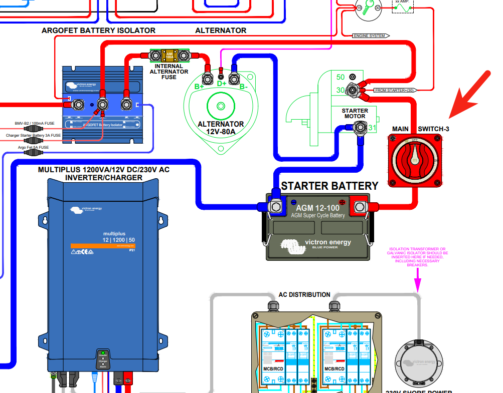
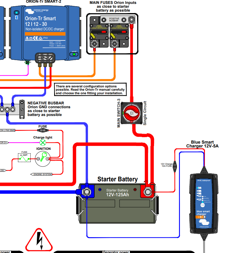
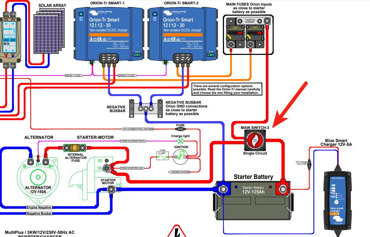
As I understand this correctly, the main switch 3 will disconnect the starter battery from the rest of the installation, but it will leave the starter motor, alternator etc. connected tot the Orion TR. I'm confused, why would you want that? To me it seems to make more sense to only disconnect the plus going to the Orion and leave the starter motor / starter battery configuration as is.

Can someone please explain this switch configuration?

Thanks!
Wilbert.

campervanswitchstarter battery
selection-854.png (267.4 KiB)
2 |3000

Up to 8 attachments (including images) can be used with a maximum of 190.8 MiB each and 286.6 MiB total.

6 Answers
gazza avatar image
gazza answered ·

When I first saw the diagram I saw one in and 2 out from the Main switch I assumed it was some sort of dual battery switch like this https://marine-electricals.co.uk/product/bep-772-dbc-pro-installer-dual-battery-bank-control-switch/# However, it does say single circuit underneath the switch, which is confusing? It is definitely good practice, essential, to include an isolator to be able to separate the starter battery and the leisure battery charging systems (some would also argue that it should be a double pole switch to switch -ve and +ve)
Either way when the switch in the diagram is OFF, the Orions will be off since they have no +ve input. They still have their -ve (common) connected to the motor/starter battery system but they are off.
I can see how you might want to be able to disconnect the starter battery from the system with that mains powered smart charger there, however, in general you would want the starter battery connected to the starter motor even if the Orion was switched out.!


2 |3000

Up to 8 attachments (including images) can be used with a maximum of 190.8 MiB each and 286.6 MiB total.

wilbert avatar image
wilbert answered ·

Thanks, that's what I figured.

I see the same weird (?) main switch location in this diagram:

selection-855.png

(Source PDF file)

Sure, the set-up is different, but I still don't get why you would disconnect the starter battery from the starter motor and leave the rest connected.


selection-855.png (192.3 KiB)
2 |3000

Up to 8 attachments (including images) can be used with a maximum of 190.8 MiB each and 286.6 MiB total.

cardy01 avatar image
cardy01 answered ·

I think you are overlooking the fundamental reason for the switch between the battery positive and the starter motor ... which is to prevent the engine being turned over (or started) maybe because some maintenance is going on ... traditionally the negative cable would be disconnected as a safety measure ... switch is less effort. With the switch in your second diagram open the Argofet and alternator are connected to each other but de-energized so it doesn't really matter.


So the switch is there for satefy and adds to the security of the (I assume boat) as someone needs to find the battery disconnect switch to steal the boat.

2 |3000

Up to 8 attachments (including images) can be used with a maximum of 190.8 MiB each and 286.6 MiB total.

pwfarnell avatar image
pwfarnell answered ·

For example on many boat electrical installation standards it is mandatory that all batteries have isolation switches, for example in the UK, the inland boats BSS (Boat Safety Scheme). If you are from a vehicle / automotive background this is uncommon except in motorsports.

2 |3000

Up to 8 attachments (including images) can be used with a maximum of 190.8 MiB each and 286.6 MiB total.

matthias-nagel avatar image
matthias-nagel answered ·

In Germany, a two-pole, isolation switch would be required directly after the battery. The purpose of that switch is not to isolate the starter battery incl. the alternator and starter from the house system, but to completely isolate the battery from the system to allow safe replacement of the battery.

Assume that you accidentally touch some metal object with the wrench while working on the plus clamp of the battery in a minus-grounded system. Then you would (accidentally) create a full short-circuit between the plus pole and the minus pole with your wrench in the middle. With a two-pole isolation switch nothing happens as the battery is fully isolated.

Of course, that requirement above does not forbid existence of another isolation switch which separates the starter system from the house system.

Yes, I am also aware that in your diagram the isolation switch is not a two-pole switch but only disconnects the plus. Hence, that arrangement fails to achieve the safety goal as described previously (because the minus remains connected), but the switch neither helps to separate the starter and house system. I can understand your confusion.

Are you sure that the system was designed by a professional? I have seen a lot of system which were designed by hobbyist and semi-professional which quite often placed a switch and/or fuse, because they thought it should go there without knowing the "why" and "wherefore". The results are usually very interesting.

2 |3000

Up to 8 attachments (including images) can be used with a maximum of 190.8 MiB each and 286.6 MiB total.

wilbert avatar image
wilbert answered ·

Thanks all for your insights!

I should've mentioned the intended purpose here is a camper van. Indeed, also here in the Netherlands, on a boat there should be a main switch to disconnect all power at once. So in that situation it would make sense.

For sure the first drawing is a Victron drawing, so I assume it designed by a professional. The second drawing has all the characteristics of a original Victron drawing, although I cannot confirm it.

In a car/camper van, to me it would make more sense to do it like this:

selection-853-edt.png

Instead of this, as per original Victron drawing:
selection-854.png

Does anyone sees any problem with my solution: a separate switched ve+ to the Orion TR's and leaving the original van's ve+ as-is?

Thanks again!


selection-853-edt.png (172.5 KiB)
selection-854.png (267.4 KiB)
2 comments
2 |3000

Up to 8 attachments (including images) can be used with a maximum of 190.8 MiB each and 286.6 MiB total.

Matthias Lange - DE avatar image Matthias Lange - DE ♦ commented ·

The Victron schematics are just examples how you CAN do it you don't have to do it like that and you always look what local regulations say.

In most cases the purpose of a main battery switch is maintenance or to disconnect the battery from any loads if the RV/boat/whatever isn't in use for some months.

0 Likes 0 ·
wilbert avatar image wilbert Matthias Lange - DE ♦ commented ·
Thanks, I can work with that!
0 Likes 0 ·

Related Resources

Additional resources still need to be added for this topic