question

rufus519 avatar image
rufus519 asked

My smart shunt 500 only shows power usage when using inverter outlets

img-0953.jpegOk so I’m hoping you all can help me figure this out or correct me if I’m wrong. So I just purchased a new travel trailer with 2 solar panels and 1 dragonfly lithium battery. I have a Xantech inverter a victron solar charger 100 and a victron smartshunt 500. Now I’ve went over and over the installation guide and I believe I have everything inputted correctly.

My issue is that the only thing the smart shunt reads is when I have things plugged into inverted outlets in the trailer. For instance I have a 12v fridge/freezer and when it is running nothing changes on the smart shunt app. Now when I plug a little fan in one of the inverter outlets it goes up and is reading the power the fan is using almost instantly.

So having this app shouldn’t I be able to read anything running off the battery not just inverted outlets? Another example if I turn on all the lights nothing changes on the app as well.

For clarification purposes in case anyone is wondering. I tested all this out with the trailer unplugged and the solar charger turned off so it was all dependent on the battery.

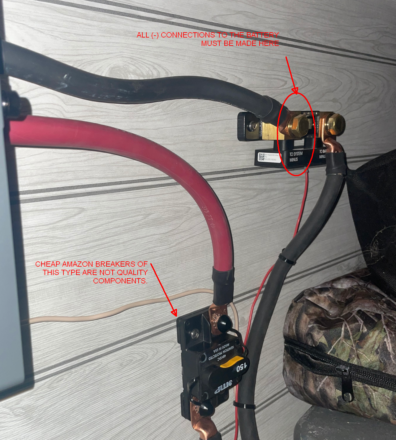
I thought I read something in another post about the trailer is possibly wired wrong because it only reads inverter outlets power usage.

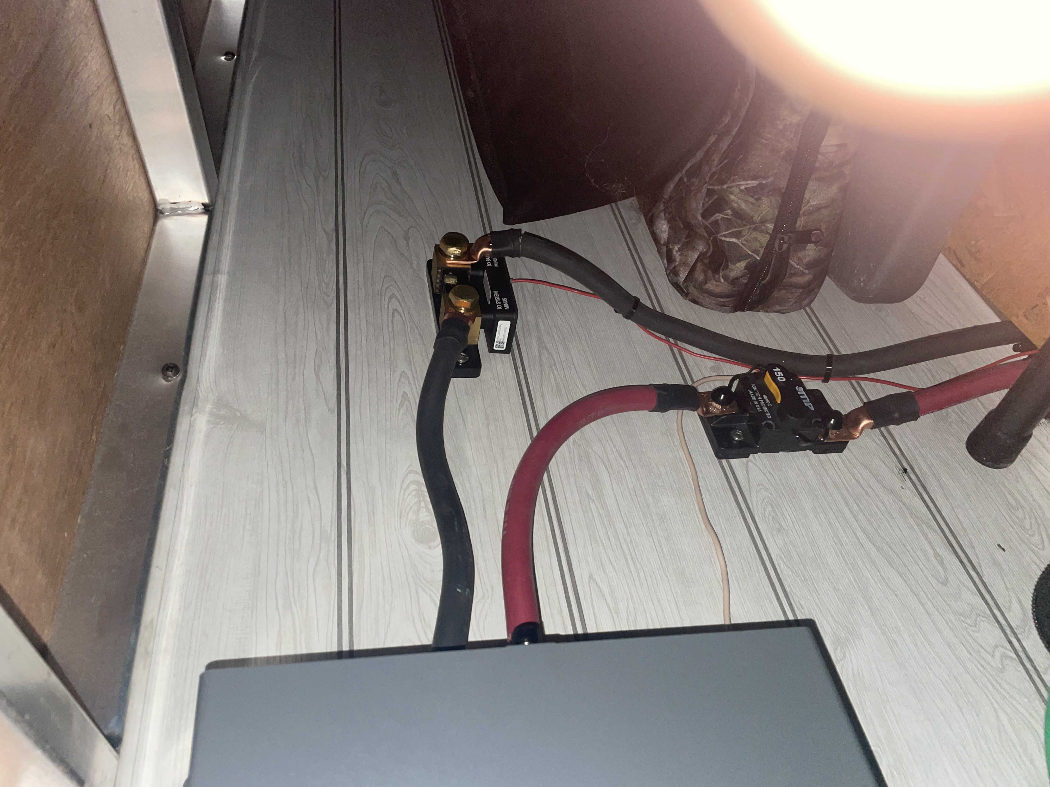
I attached 2 pictures of how the shunt is wired as well in case it’s not wired correctly. The grey box on the left is the inverter.


img-0951.jpeg


SmartShunt
img-0951.jpeg (2.6 MiB)
img-0953.jpeg (2.7 MiB)
2 |3000

Up to 8 attachments (including images) can be used with a maximum of 190.8 MiB each and 286.6 MiB total.

8 Answers
Matthias Lange - DE avatar image
Matthias Lange - DE answered ·

Read the manual again, the Shunt is not installed correctly.

The way you installed it, it can only see the current of the inverter.

(I guess the gray box on the left side is the inverter)

The shunt has to be the only thing connected to the battery (battery side) and everything else (loads and charger) have to be connected to the "system side" of the shunt.

I don't get it why this is such a common installation problem. The manual can't be any clearer about that.

3 comments
2 |3000

Up to 8 attachments (including images) can be used with a maximum of 190.8 MiB each and 286.6 MiB total.

rufus519 avatar image rufus519 commented ·

Yeah I didn’t install it. The dealer installed it like this I got the trailer a week ago. So I’ll have to bring it back and get them to fix it! Thank you very much for your help.

0 Likes 0 ·
rufus519 avatar image rufus519 commented ·

I just wanna be clear when I contact the dealer. The black wire on the right which says battery minus goes directly to the battery on the tongue of the trailer. The black wire on the left goes to the inverter and it is on the “system minus” terminal. So where should the wire on the left go then? Cause I’m assuming the black wire on the right is in the right spot (shunt to battery)

0 Likes 0 ·
Matthias Lange - DE avatar image Matthias Lange - DE ♦ rufus519 commented ·
Just say them they have to RTFM(!). The manual is very clear about how to install it and there are also videos available on YouTube.


On the battery negative should only be one wire and that is going to the "battery negative" side of the shunt.

The negative of ALL(!) loads and charger have to be on the "system minus" side of the shunt.
0 Likes 0 ·
seb71 avatar image
seb71 answered ·

Is that grey box the inverter?

If not, where the wires are going? Photos with with just parts of your system are not that usefull.

If you have a wire diagram, that would be even better (as long as it corresponds with reality).


So where should the wire on the left go then?

You could stack all your negative wires there (from inverter, from loads, from MPPT chargers), but that is not recommended. You should have just one wire lug on a bolt.

Proper way is to use busbars (for negative and for positive). This way you have multiple bolts, one for each wire lug. For very small wires it is acceptable to stack a few wire lugs on a bolt, but still not desirable.

2 |3000

Up to 8 attachments (including images) can be used with a maximum of 190.8 MiB each and 286.6 MiB total.

rufus519 avatar image
rufus519 answered ·

img-0957.jpeg
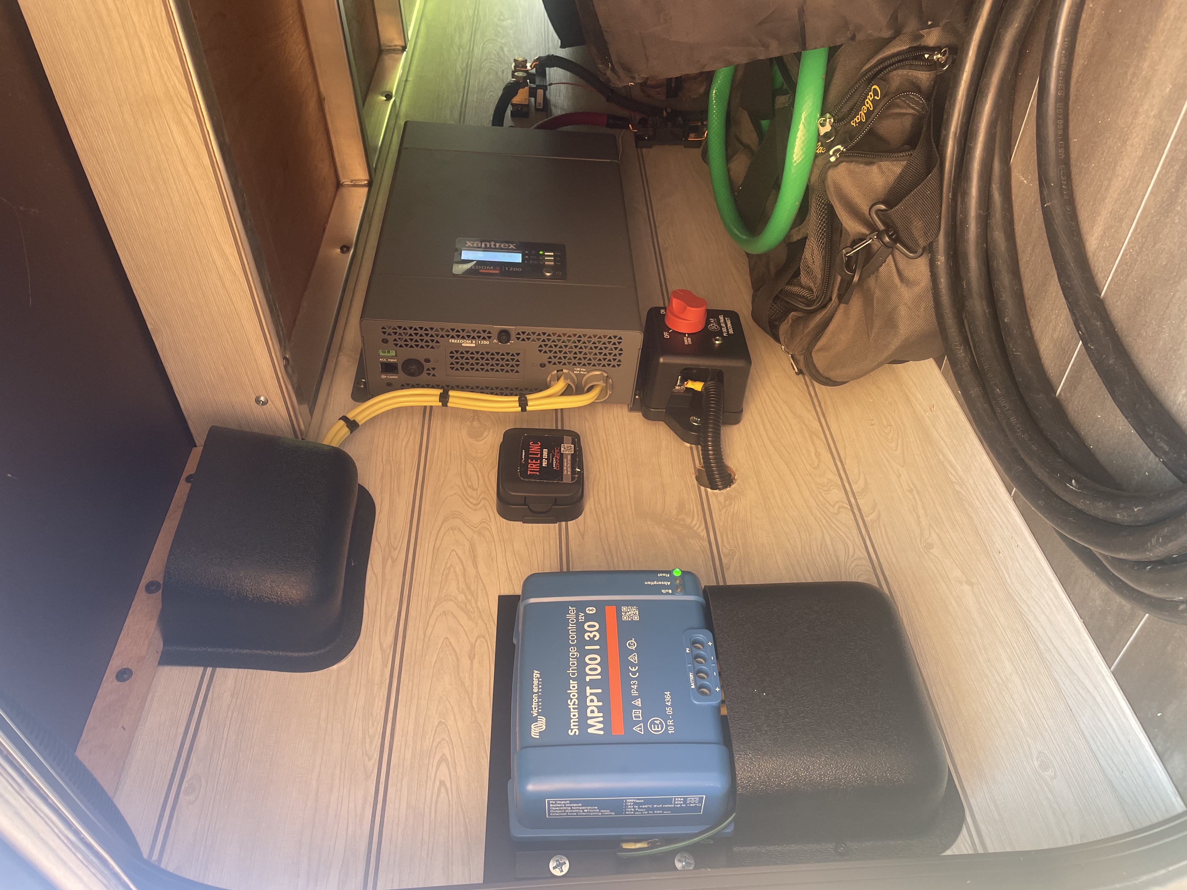
Here’s a better picture of the whole system. The battery minus wire goes directly to the battery and the one on the left of the shunt goes to the inverter (big grey box).

Do I need to bring that system wire all the way over to the blue charge controller?


img-0957.jpeg (2.9 MiB)
1 comment
2 |3000

Up to 8 attachments (including images) can be used with a maximum of 190.8 MiB each and 286.6 MiB total.

Matthias Lange - DE avatar image Matthias Lange - DE ♦ commented ·

The negative of ALL!!!! loads and charger (the inverter, the MPPT, other changes,ALL other loads and also the chassis) have to be on the system side of the shunt.

There should be no other cable on the negative terminal of the battery than the one going to the shunt.

The shunt can only "see" current that is going through it, loads/charger that are connected directly to the battery will bypass the shunt and can't be shown in the app.

Look at the manual!

https://www.victronenergy.com/upload/documents/Datasheet-SmartShunt-EN.pdf

https://www.victronenergy.com/media/pg/SmartShunt/en/index-en.html

0 Likes 0 ·
seb71 avatar image
seb71 answered ·
2 |3000

Up to 8 attachments (including images) can be used with a maximum of 190.8 MiB each and 286.6 MiB total.

snoobler avatar image
snoobler answered ·

Please see the following:


1692473412106.png


Anything connected to the battery (-) that does not pass through this terminal are bypassing the shunt, and the shunt can't see that current.


1692473375666.png (3.2 MiB)
1692473412106.png (3.2 MiB)
2 |3000

Up to 8 attachments (including images) can be used with a maximum of 190.8 MiB each and 286.6 MiB total.

rufus519 avatar image
rufus519 answered ·

Thank you snoobler . This helps me understand more. Sorry I’m not an electrician, actually I’m a pipe fitter by trade.

Are you able to explain what the fix for this would ultimately would be with the information and pictures I have given? We bought this camper for the purpose of off grid camping, so I really wanna understand and make sure it’s working to its full capabilities at the same time learning all I can about the unit it’s self.

1 comment
2 |3000

Up to 8 attachments (including images) can be used with a maximum of 190.8 MiB each and 286.6 MiB total.

snoobler avatar image snoobler commented ·
Every connection to the battery (-) must be made at the circled terminal, i.e., all loads and chargers (-) must attach there.
0 Likes 0 ·
rufus519 avatar image
rufus519 answered ·

I should probably add this as well. I have a battery distribution box on the tongue next to the battery. It has 2 black wires coming off the battery one goes to the shunt the other to the battery distribution box. And I wrong in thinking that the shunt should have a a black wire going to the battery distribution box as well? Or is that the incorrect fix? img-0960.jpegimg-0959.jpeg


img-0959.jpeg (3.1 MiB)
img-0960.jpeg (4.1 MiB)
3 comments
2 |3000

Up to 8 attachments (including images) can be used with a maximum of 190.8 MiB each and 286.6 MiB total.

snoobler avatar image snoobler commented ·
Anything drawing or sending power through the distribution box is bypassing the shunt.


Battery (-) -> Shunt -> everything else.


I believe that if you disconnected the battery (-) cable that goes to the distribution box FROM THE BATTERY (-) and moved it to the circled terminal on the shunt, it would resolve the issue.

0 Likes 0 ·
rufus519 avatar image rufus519 snoobler commented ·
So I just did a test. I disconnected the power from the trailer, shut off the solar panels and shut off the battery disconnect. And wouldn’t you know it the inverter stays on. all 8 of the inverted outlets still work. So the inverter is by passing the battery disconnect completely and staying on when everything should be shut down.


So disconnecting the wire that goes from the battery to the disconnect box. I should move that wire so it’s hooked up to the disconnect box and the system side of the shunt? Is there anything that would need to be done to the red positive wires?

0 Likes 0 ·
snoobler avatar image snoobler rufus519 commented ·
Battery (-) > shunt > everything else (disconnect box, inverter, etc.)


The disconnect is typically on the (+) side to prevent breaking system ground.


Battery (-) > fuse or breaker > disconnect > everything else.


To use the cutoff switch in the disconnect box, the (+) to the inverter must pass through it.


The existing disconnect and the breaker between the inverter and battery can be used together to completely isolate the battery.


0 Likes 0 ·
seb71 avatar image
seb71 answered ·

Sorry I’m not an electrician, actually I’m a pipe fitter by trade.

Think of the battery negative terminal as a well pump and the shunt like it's a water meter.


You want all the water from the well to pass through that water meter.


So all pipe ramifications you need (to divert water in various places) should be after the water meter.


As you have it now, it appears that you have some pipe ramifications between the well pump and the water meter.


Note:

This analogy only covers the negative wires.

2 |3000

Up to 8 attachments (including images) can be used with a maximum of 190.8 MiB each and 286.6 MiB total.